Multicore fiber

a fiber and multi-core technology, applied in the field of multi-core fibers, can solve the problems of optical interference between adjacent cores, increased connection loss, and small mode field diameter,

Active Publication Date: 2012-08-02
THE FUJIKURA CABLE WORKS LTD
View PDF6 Cites 26 Cited by
  • Summary
  • Abstract
  • Description
  • Claims
  • Application Information

AI Technical Summary

Benefits of technology

[0020]As described above, with the present invention, a multicore fiber enabling

Problems solved by technology

However, if the relative refractive index difference is heightened as in the multicore fiber described in Non-Patent Document 1, the mode field diameter may become too small, and a connection loss may be increased in the optical transmission system in which the multicore fibers are connected to one another.
O

Method used


Image

  • Multicore fiber
  • Multicore fiber
  • Multicore fiber

Examples


first embodiment

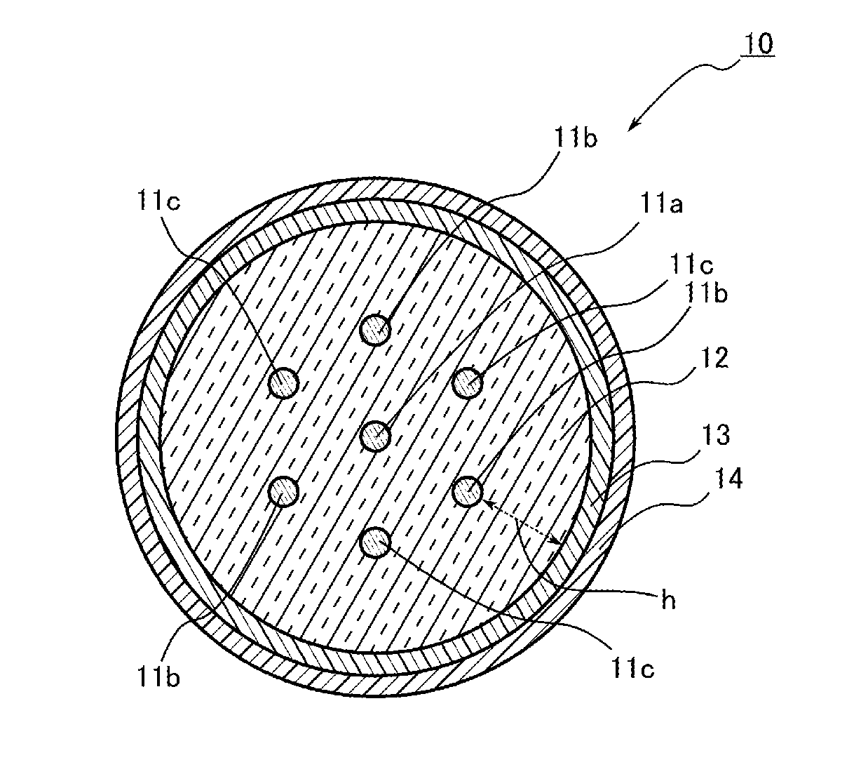
[0036]FIG. 1 is a cross-sectional view illustrating a state in a cross-section perpendicular to a longitudinal direction of a multicore fiber according to an embodiment of the present invention.

[0037]As illustrated in FIG. 1, a multicore fiber 10 includes plural cores 11a, 11b, and 11c having different diameters from one another, a clad 12 covering the outer circumferences of the respective cores 11a, 11b, and 11c, an inner protective layer 13 covering the outer circumference of the clad 12, and an outer protective layer 14 covering the outer circumference of the inner protective layer 13. It is to be noted that FIG. 1 shows a case in which the total number of cores is 7.

[0038]The plural cores 11a, 11b, and 11c are arranged to have predetermined spaces on the cross-section of the multicore fiber 10. Specifically, one core 11a is arranged at the center of the clad 12, and plural cores 11b and plural cores 11c are arranged alternately in a circumferential direction around the core 11a...

second embodiment

[0071]Next, a second embodiment of the present invention will be described in details with reference to FIG. 11. It is to be noted that similar or identical components to those in the first embodiment are shown with the same reference numerals, and description of the duplicate components is omitted. FIG. 11 is a cross-sectional view illustrating a state in a cross-section perpendicular to a longitudinal direction of a multicore fiber according to the second embodiment of the present invention.

[0072]As illustrated in FIG. 11, a multicore fiber 20 in the present embodiment has 19 cores. These cores include three kinds of cores 11a, 11b, and 11c, and the core 11a is arranged at the center on the cross-section of the multicore fiber 20. The respective cores are arranged in a triangular lattice shape with a core 11a, a core 11b, and a core 11c as a set. In this manner, the adjacent cores have different diameters from one another. In the present embodiment as well, arranging the cores 11a...

example 1

[0086]In a similar manner to the first embodiment, a multicore fiber having a length of 2.5 km was produced. In the multicore fiber, the diameter of the clad was 142 μm, a core having a diameter of 6.0 μm was arranged at the center while 6 cores that were different from the core arranged at the center only in terms of the diameters were arranged around the core arranged at the center. The center-to-center distance between the cores was 40 μm each, the shortest distance between the outer circumference of the core arranged around the center core and the outer circumference of the clad was 28 μm, and the respective cores were arranged in a triangular lattice shape. When the diameter of each core was confirmed in a state of a base material before it was filled in the fiber, the diameters of the adjacent cores differed from the average of the diameters of the two cores by 0.3% or more and less than 5%. Further, quartz containing 6.8 mol % of germanium oxide (GeO2) was used for each core...


PUM


Abstract

The multicore fiber comprises 7 or more cores, wherein diameters of the adjacent cores differ from one another, wherein each of the cores performs single-mode propagation, wherein a relative refractive index difference of each of the cores is less than 1.4%, wherein a distance between the adjacent cores is less than 50 μm, wherein, in a case where a transmission wavelength of each of the cores is λ, the distance between the adjacent cores is , a mode field diameter of each of the cores is MFD, and a theoretical cutoff wavelength of each of the cores is λc, (/MFD)·(2λc/(λc+λ))≧3.95 is satisfied, and wherein a distance between the outer circumference of the coreand an outer circumference of the clad is 2.5 or higher times as long as the mode field diameter of each of the cores.

Description

CROSS-REFERENCE TO RELATED APPLICATIONS[0001]This application is a Continuation of copending PCT International Application No. PCT / JP2010 / 064280 filed on Aug. 24, 2010, which designated the United States, and on which priority is claimed under 35 U.S.C. §120. This application also claims priority under 35 U.S.C. §119(a) on Patent Application No. 2009-199094 filed in Japan on Aug. 28, 2009. The entire contents of each of the above documents are hereby incorporated by reference into the present application.TECHNICAL FIELD[0002]The present invention relates to a multicore fiber.BACKGROUND ART[0003]Currently, an optical fiber used in a popularized optical fiber transmission system has a configuration in which the outer circumference of a core is covered with a clad, and an optical signal is propagated in the core to cause information to be transmitted. Recently, along with the popularization of the optical fiber transmission system, the amount of information to be transmitted by the opt...

Claims


Application Information

Patent Timeline
IPC IPC(8): G02B6/02
CPCG02B6/02042
Inventor TAKENAGA, KATSUHIROGUAN, NINGTANIGAWA, SYOUJI
Owner THE FUJIKURA CABLE WORKS LTD
Why Eureka
Try Eureka