Shockproof fan apparatus

Inactive Publication Date: 2012-08-02
HONG FU JIN PRECISION IND (SHENZHEN) CO LTD +1
View PDF30 Cites 9 Cited by
  • Summary
  • Abstract
  • Description
  • Claims
  • Application Information

AI Technical Summary

Problems solved by technology

However, while rotating, the fan blades may collide with the case due to vibration of the fan.
This could damage the fan blades or the case.

Method used


Image

  • Shockproof fan apparatus
  • Shockproof fan apparatus
  • Shockproof fan apparatus

Examples


Embodiment Construction

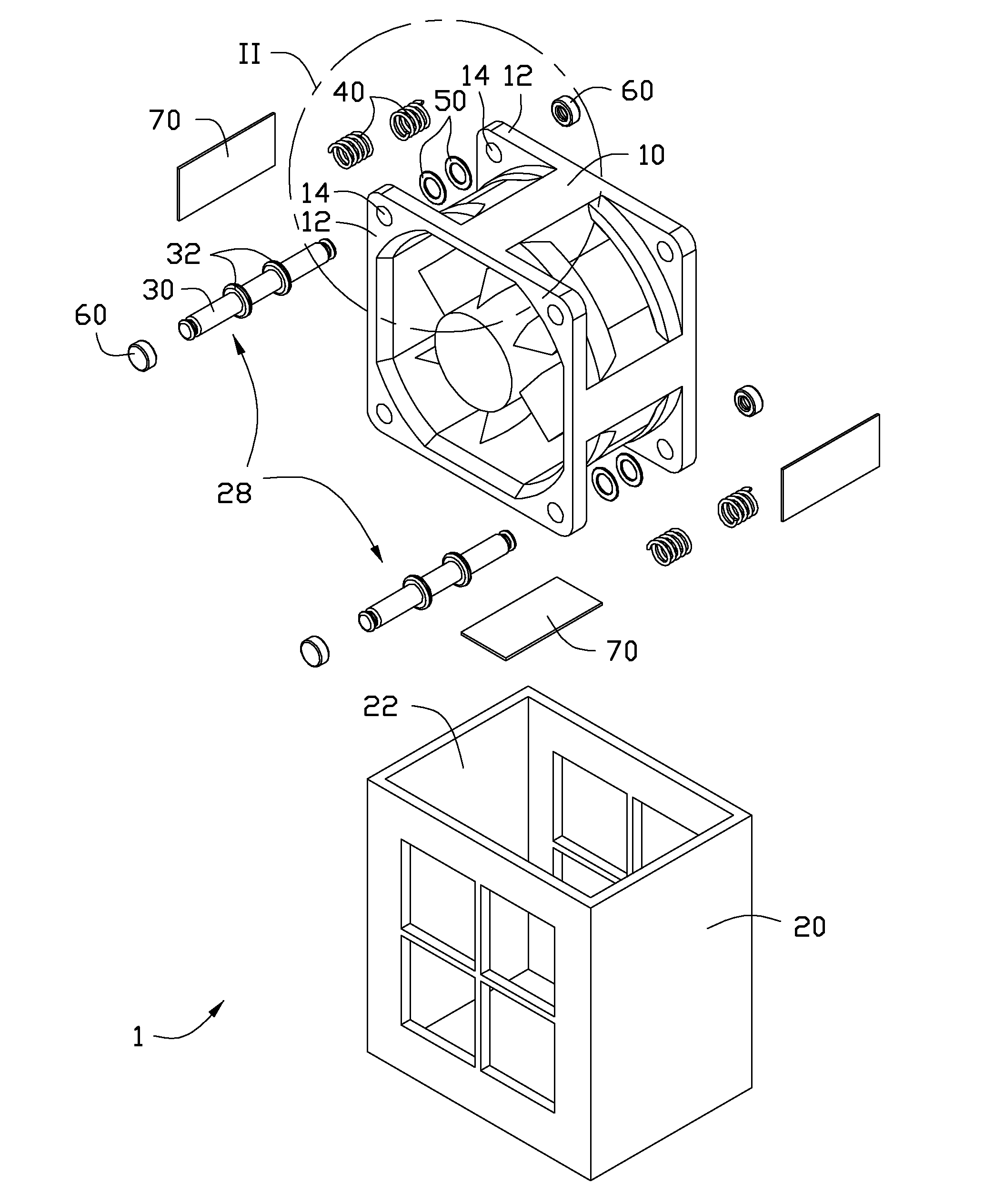
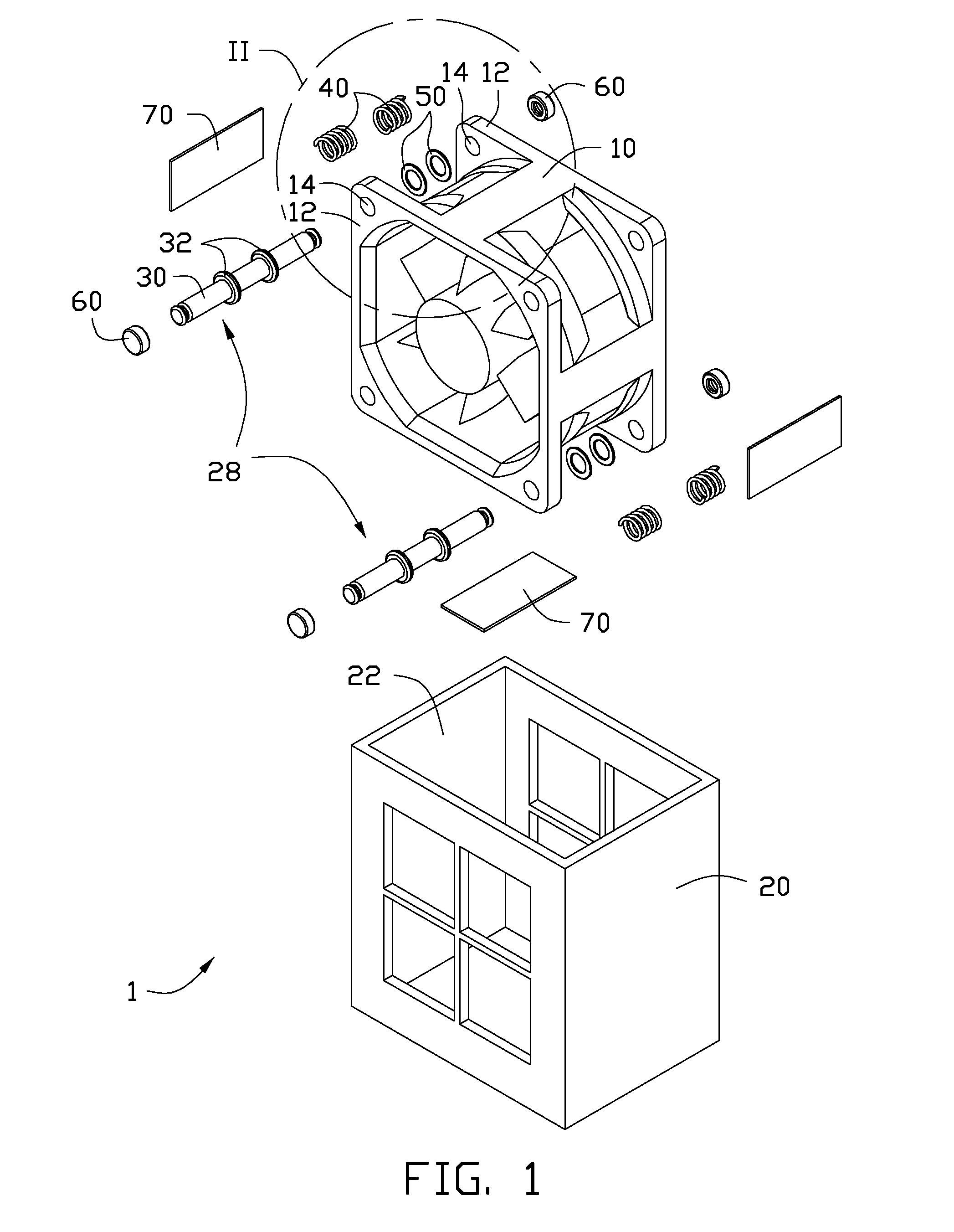
[0011]FIG. 1 showing an exploded, isometric view of a fan apparatus 1. The fan apparatus 1 includes a fan 10 having two square-shaped plates 12 thereon, and four through holes 14 are defined on four corners of each plate 12; each through hole 14 corresponds to one of the through holes 14 of the other plate 12. The fan apparatus 1 further includes a case 20 to receive the fan 10, and two shockproof units 28 and a number of spacers 70 to apply shockproof capability to the fan apparatus 1.

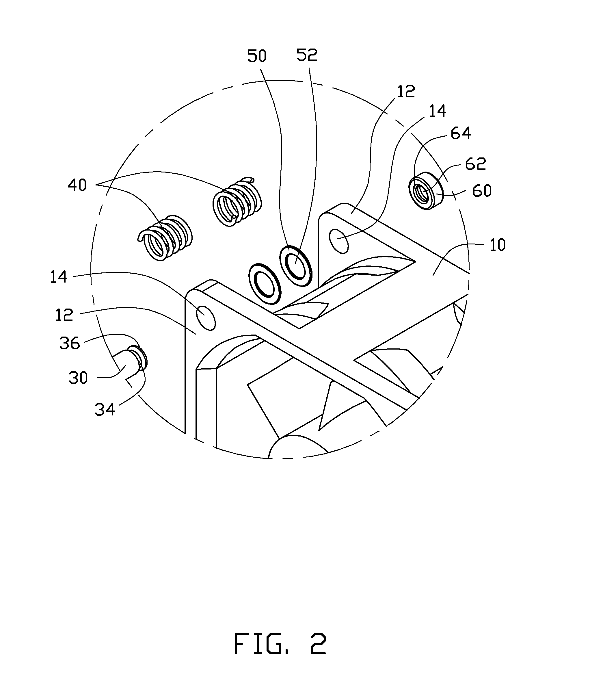
[0012]Each shockproof unit 28 includes a pole 30, two elastic element 40, two gaskets 50 and two sleeves 60, and two flanges 32 are defined on the pole 30. Referring to FIG. 2, two concave grooves 34 are defined on the two ends of the pole 30, forming two fastening sections 36 at the two ends of the pole 30. Each gasket 50 has a hole in the center, and the sleeve 60 has a containing hole 62 therein. A protrusion 64 is defined on the sleeve 60 to fasten to the concave groove 34 of the pole 30. In the p...


PUM


Abstract

A fan apparatus includes a fan, a shockproof unit, and a case. The fan includes two plates, and a through hole is defined on each plate. The shockproof unit includes a pole penetrating the two though holes, and at least a flange is defined on the pole; at least an elastic element is restricted between one of the plates and the flange. Two ends of the pole protrude from the through holes and abut on the case when the fan is received in the case. A concave groove is defined on each end of the pole; the concave groove protrudes one of the through holes and received in a sleeve abutting on the case; a containing hole is defined in the sleeve to receive the end of the pole.

Description

BACKGROUND[0001]1. Technical Field[0002]The present disclosure relates to a fan apparatus, and particularly, to a shockproof fan apparatus.[0003]2. Description of Related Art[0004]An electronic device often uses a fan for heat dissipation, the fan is installed in a case mounted in the electronic device. However, while rotating, the fan blades may collide with the case due to vibration of the fan. This could damage the fan blades or the case.[0005]Therefore, what is needed is a fan apparatus that overcomes these limitations.BRIEF DESCRIPTION OF THE DRAWINGS[0006]The components in the drawings are not necessarily drawn to scale, the emphasis instead being placed upon clearly illustrating the principles of a shockproof fan apparatus. Moreover, in the drawings, like reference numerals designate corresponding parts throughout the several views.[0007]FIG. 1 is an exploded, isometric view of a fan apparatus in accordance with an exemplary embodiment.[0008]FIG. 2 is an enlarged view of sect...

Claims


Application Information

Patent Timeline
IPC IPC(8): F04D29/66
CPCH05K7/20172F04D25/0613F04D29/668F04D29/601F04D29/60
Inventor CHAN, HUNG-CHOU
Owner HONG FU JIN PRECISION IND (SHENZHEN) CO LTD
Why Eureka
Try Eureka