Instrument and method for implanting an interbody fusion device

a technology of interbody fusion and instrument, which is applied in the field of spinal fixation and fusion systems, can solve the problems of destabilizing the spinal column, difficult alignment, and difficulty in correct alignment and spacing of holes

Inactive Publication Date: 2003-02-25
ZIMMER SPINE INC
View PDF105 Cites 332 Cited by
  • Summary
  • Abstract
  • Description
  • Claims
  • Application Information

AI Technical Summary

Problems solved by technology

Removal or partial removal of an intervertebral disc may destabilize the spinal column.
Protective sleeve 30 has characteristics that may make achieving alignment difficult.
It is often difficult to align and space the holes correctly.
Any slight movement of protective sleeve 30, which may act like a lever arm, may result in misalignment of the hole.
Any slight movement of sleeve 40, which may act like a lever arm, may result in misalignment of the holes.
Second, the long parallel tubes make it difficult to angulate the two implants 52 relative to each other.
The sleeve tends to act like a lever arm, and any slight motion of the sleeve during the procedure may result in misalignment of the implants.
The sleeve acting as a lever arm is particularly problematic when the sleeve is handed off during the surgical procedure from one member of the surgical team to another member of the surgical team.
A second disadvantage of protective sleeves is related to the first disadvantage.
This connection may not be very secure.
Because the connection is not secure, the sleeve may have to be held by the members of the surgical team throughout the entire procedure to maintain proper alignment.
As noted above, any slight movement can result in the misalignment of the implants.
A third disadvantage of protective sleeves is that they may afford minimal protection to surrounding tissues during a spinal fusion procedure.
The interface between the distal end of the sleeve and the spinal column is typically not a perfect fit.
The presence of gaps creates the risk of drill bits, taps, and implants coming into contact with the blood vessels or other tissue during the procedure.
A nick or cut to a major blood vessel can be life threatening.
The above-mentioned methods and systems inadequately address the need to angulate implants in some spinal fusion procedures, the need to maintain precise alignment throughout the procedure, and the need to protect surrounding tissues during the procedure.
The flange may inhibit tissue from being pinched, nicked, or otherwise harmed during the spinal fusion procedure.
Removal of a protective sleeve from the holder may decrease the likelihood of a protective sleeve being inadvertently used as a lever arm during the procedure.

Method used


Image

  • Instrument and method for implanting an interbody fusion device
  • Instrument and method for implanting an interbody fusion device
  • Instrument and method for implanting an interbody fusion device

Examples


Embodiment Construction

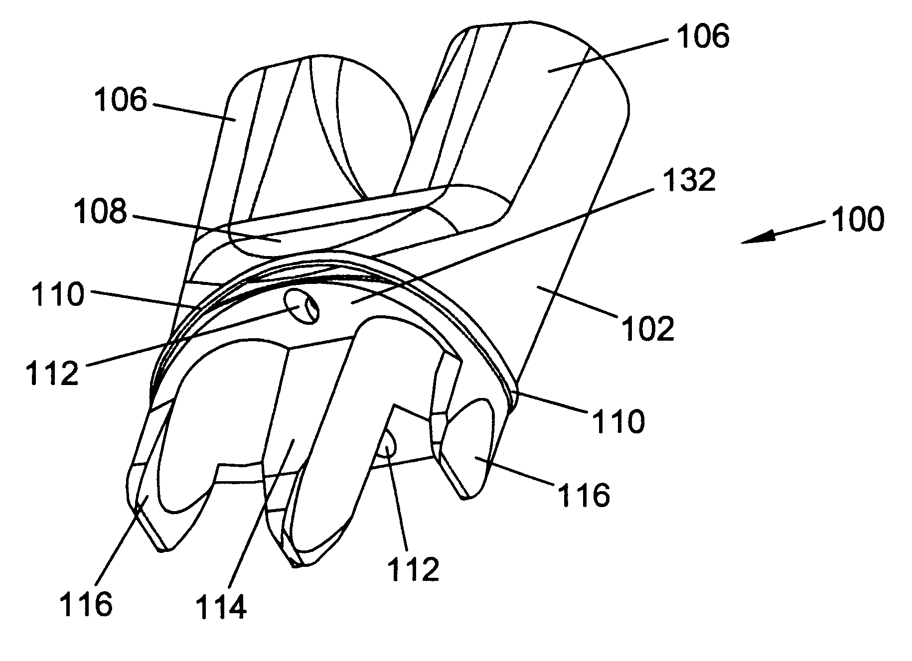
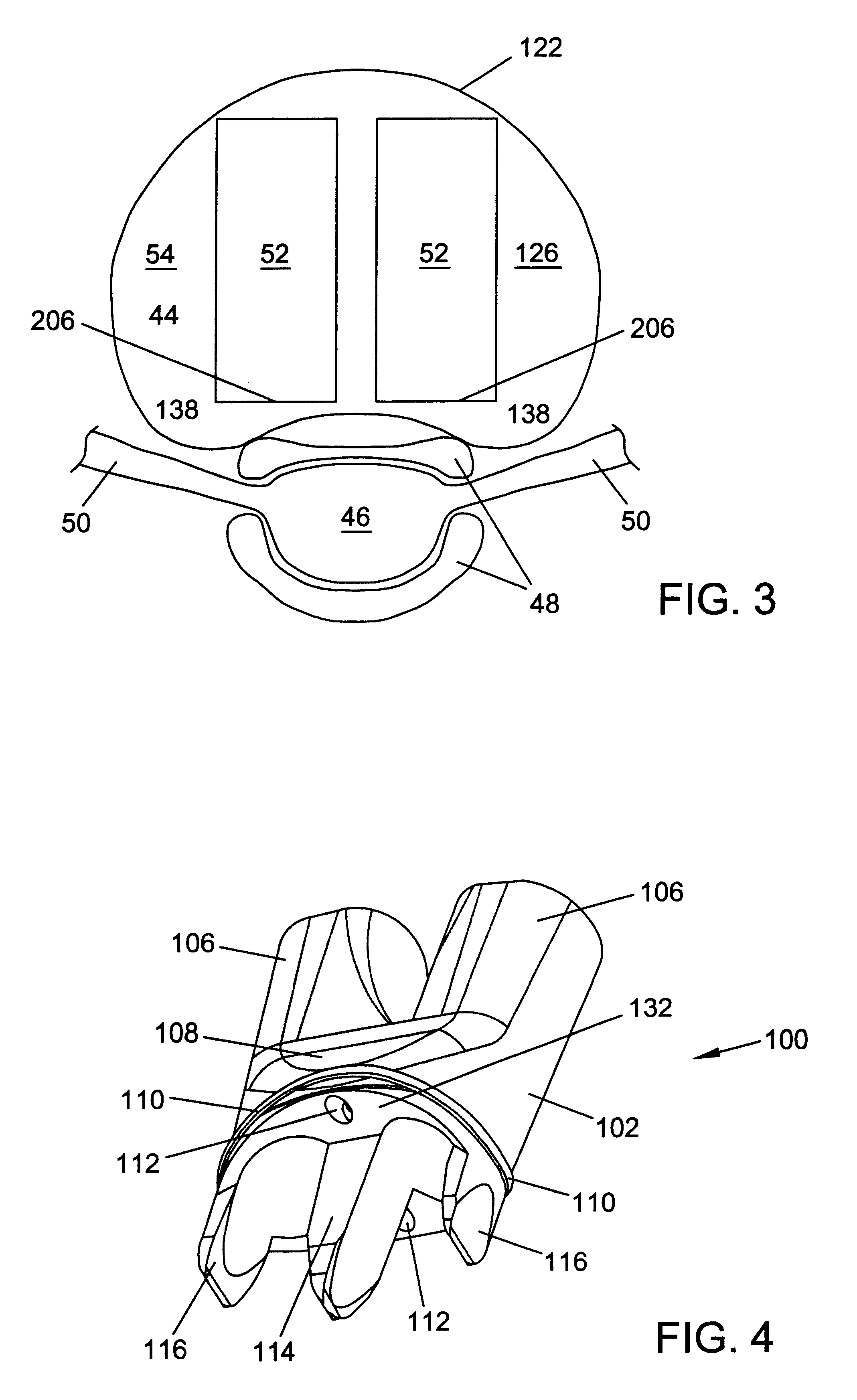
Referring to the drawings, and particularly to FIG. 4, a holder or base that may be used as an implant insertion guide during a spinal fusion procedure is designated generally as 100. A holder may be used to support a sleeve during a spinal fusion procedure. A base may be used with or without a sleeve during a spinal fusion procedure. For illustrative purposes only, the following description will describe a holder. A person having ordinary skill in the art will understand that a holder may be used as a base, and a base may be used as a holder. A sleeve may be advantageously used during an implant insertion procedure. A top surface of the sleeve may be a stop for an instrument that limits an insertion depth of the instrument into a disc space.

FIGS. 4-10 show views of embodiments of holders 100. A holder 100 may include body 102, conduits 104 through the body, conduit extenders 106, flared portion 108, flange rim 110, fastener holes 112 distractor 114, and lateral distractors 116. In ...


PUM


Abstract

A holder is provided which couples to the spine. In an embodiment, the holder has two conduits into which sleeves may be inserted during a spinal fusion procedure. The holder may have a distractor extending from the bottom of the holder. The distractor secures the holder to the spine and maintains a proper separation distance between adjacent vertebrae. The sides of the distractor may be serrated to better secure the holder to the spine. The sleeves and conduits serve as alignment guides for instruments and implants used during the procedure. In an embodiment, the holder may include holes for fasteners that fixably secure the holder to vertebrae adjacent to a disc space. A flange may be placed around the holder to shield surrounding tissue and to provide a placement location for adjacent blood vessels during the spinal fusion procedure.

Description

1. Field of the InventionThe present invention generally relates to spinal fixation and fusion systems. An embodiment of the present invention relates to an insertion guide used during the insertion of a spinal implant into a disc space between a pair of vertebrae. The implant may be used for correction, fixation, and / or stabilization of a spinal column.2. Description of the Related ArtAn intervertebral disc that becomes degenerated may have to be partially or fully removed from a spinal column. Intervertebral discs may become degenerated due to various causes such as trauma, disease, or aging. Removal or partial removal of an intervertebral disc may destabilize the spinal column. A spinal implant may be inserted into a disc space created by the removal or partial removal of an intervertebral disc. The spinal implant may maintain the height of the spine and restore stability to the spine. Bone may grow from adjacent vertebrae into the spinal implant. The bone growth may fuse the adj...

Claims


Application Information

Patent Timeline
Patent Type & Authority Patents(United States)
IPC IPC(8): A61B17/16A61B17/17A61F2/46A61F2/00A61F2/44A61B17/02
CPCA61B17/1757A61F2/4611A61B2017/0256A61F2/442A61F2/446A61F2002/4687A61F2002/448A61F2002/4627A61F2002/4681A61F2250/0063A61F2002/30611A61F2002/30604
Inventor LANDRY, MICHAEL E.WAGNER, ERIK J.HOCHSCHULER, STEPHEN H.KRUEGER, DAVID J.
Owner ZIMMER SPINE INC
Why Eureka
Try Eureka