Balancing discharge area developed and transferred toner

Inactive Publication Date: 2012-08-02
EASTMAN KODAK CO
View PDF4 Cites 5 Cited by
  • Summary
  • Abstract
  • Description
  • Claims
  • Application Information

AI Technical Summary

Benefits of technology

[0032]FIGS. 8A-8C provide illustrations depicting the operation of the method of FIG. 6 to reduce stack height variations according to a first extent.
[0033]FIGS. 9A-9B conceptually illustrate effects of the method of FIG. 7 at different engine pixel locations to reduce the range of toner stack height variations.
[0034]FIGS. 10A-10C provide illustrations depicting the operation of the method of FIG. 7 to provide a toner overcoat of a different amount to reduce

Problems solved by technology

However, differences in the amount of color separation toner applied to form different colors form what are known as toner stacks and can cause different the toner stacks to have a different toner stack heights.
The relief differentials disrupt the flatness of the exterior surface of such a color toner image.
These relief differentials cause light to reflect along different paths and this, in turn, reduces the apparent gloss of the fused toner image.
Accordingly, while the net difference of potential at the start of a development step can be high, this net difference of potential decreases as development progresses, slowing the development process and effectively limiting the o

Method used


Image

  • Balancing discharge area developed and transferred toner
  • Balancing discharge area developed and transferred toner
  • Balancing discharge area developed and transferred toner

Examples


Embodiment Construction

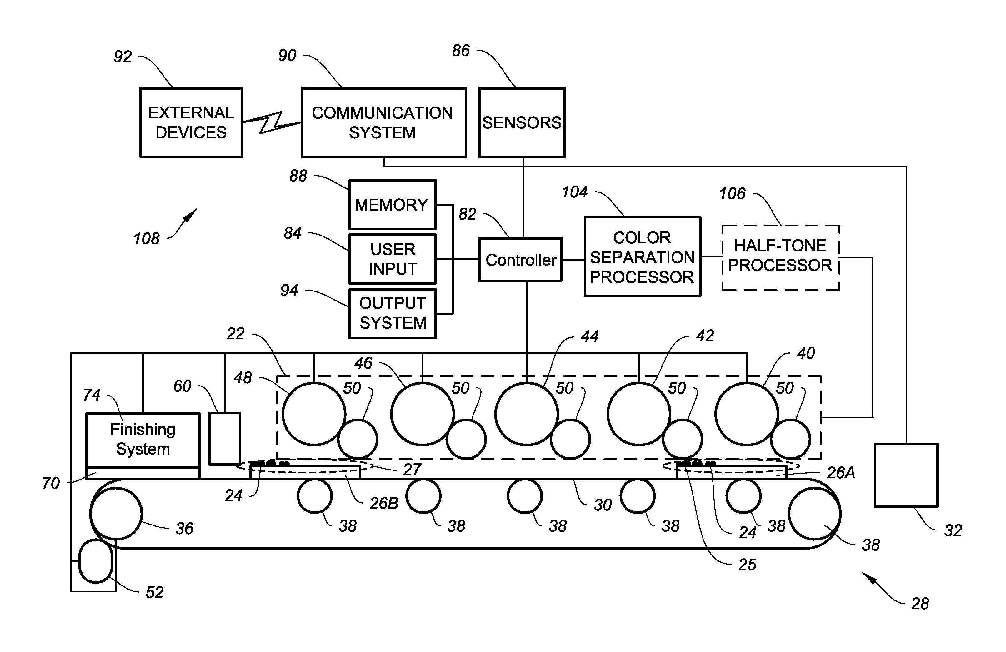
[0037]FIG. 3 is a system level illustration of a printer 20. In the embodiment of FIG. 3, printer 20 has a print engine 22 of an electrophotographic type that deposits toner 24 to form a toner image 25 in the form of a patterned arrangement of toner stacks. Toner image 25 can include any patternwise application of toner 24 and can be mapped according to data representing text, graphics, photo, and other types of visual content, as well as patterns that are determined based upon desirable structural or functional arrangements of the toner 24.

[0038]Toner 24 is a material or mixture that contains toner particles and that can form an image, pattern, or indicia when electrostatically deposited on an imaging member including a photoreceptor, photoconductor, electrostatically-charged, or magnetic surface. As used herein, “toner particles” are the particles that are electrostatically transferred by print engine 22 to form a pattern of material on a receiver 26 to convert an electrostatic la...


PUM


Abstract

Printing methods are provided. In one aspect, at least one first toner image is formed and transferred onto a receiver to form a composite toner image on a receiver having a first polarity. A second net development difference of potential of the first polarity is created between a second development station, a bias member and the first toner at each location of the receiver, to cause a second toner of the first polarity to deposit at individual locations on the receiver in amounts that according to the second net development difference of potential at the individual locations such that total amount of first toner and any second toner deposited at each location on the receiver is within a range that is less than a range of first toner amounts on the receiver.

Description

CROSS REFERENCE TO RELATED APPLICATIONS[0001]This application relates to commonly assigned, copending U.S. application Ser. No. ______ (Docket No. 96671RRS), filed ______, entitled: “ENHANCEMENT OF DISCHARGED AREA DEVELOPED TONER LAYER”; U.S. application Ser. No. ______ (Docket No. 96775RRS), filed ______, entitled: “ENHANCEMENT OF CHARGE AREA DEVELOPED TONER LAYER”; U.S. application Ser. No. ______ (Docket No. 96777RRS), filed ______, entitled: “BALANCING CHARGE AREA DEVELOPED AND TRANSFERRED TONER”; U.S. application Ser. No. ______, (Docket No. 96778RRS), filed ______, entitled: “PRINTER WITH DISCHARGE AREA DEVELOPED TONER BALANCING”; and U.S. application Ser. No. ______ (Docket No. 96779RRS), filed ______, entitled: “PRINTER WITH CHARGE AREA DEVELOPED TONER BALANCING”; each of which is hereby incorporated by reference.FIELD OF THE INVENTION[0002]This invention pertains to the field of printing.BACKGROUND OF THE INVENTION[0003]In color electrophotography, a full color image is bui...

Claims


Application Information

Patent Timeline
IPC IPC(8): G03G13/16G03G13/20
CPCG03G13/16G03G13/20G03G15/0194G03G15/0126G03G15/6585
Inventor FOWLKES, WILLIAM Y.
Owner EASTMAN KODAK CO
Why Eureka
Try Eureka