Steering device

a steering device and steering wheel technology, applied in the direction of steering parts, vehicle components, transportation and packaging, etc., can solve the problems of difficult constant restoring force maintenance, inability to smoothly move in the axial direction, and inability to comfortably perform telescopic adjustment, so as to reduce the number of parts and assembly operations, prevent the steering wheel from falling, and reduce the cost

Inactive Publication Date: 2012-08-09
YAMADA SEISAKUSHO KK
View PDF10 Cites 19 Cited by
  • Summary
  • Abstract
  • Description
  • Claims
  • Application Information

AI Technical Summary

Benefits of technology

[0018]In the second aspect of the invention, the pushing member is configured to have a spring portion as means for elastically biasing the expanding shaft portion to both sides of the expanding shaft portion in the width direction. Therefore, the pushing member can be imparted with a function of expanding the fastening pieces and a function of preventing the steering wheel from falling down under gravity when the lock is released during the tilt-telescopic operation.
[0019]Further, by forming the expanding shaft portion and the spring portions integrally in the pushing member it is possible to decrease the number of parts and assembly operations, thereby reducing cost.
[0020]In the third aspect of the present invention, the expanding shaft portion of the pushing member is formed to have a peak-like shape. Therefore, the two fastening pieces of the embracing body portion can be pushed and expanded uniformly to the left and to the right, and the telescopic adjustment can be performed with higher effectiveness, without a significant difference between a contact pressure of one fastening pieces and that of the other fastening pieces. Further, when the expanding shaft portion is formed as a circular-arc peak, the expanding shaft portion has a substantially arch-like shape and the entire structure has high strength and durability.
[0021]Further, when the expanding shaft portion of the pushing member is formed to

Problems solved by technology

Therefore, when telescopic adjustment is performed, the friction force becomes equal to or greater than the adequate force, the inner column 1 cannot be smoothly moved in the axial direction, and the telescopic adjustment cannot be comfortably performed.
However, the restoring force of the spring member SPG changes according to the opening degree of the outer column, and

Method used


Image

  • Steering device
  • Steering device
  • Steering device

Examples


first embodiment

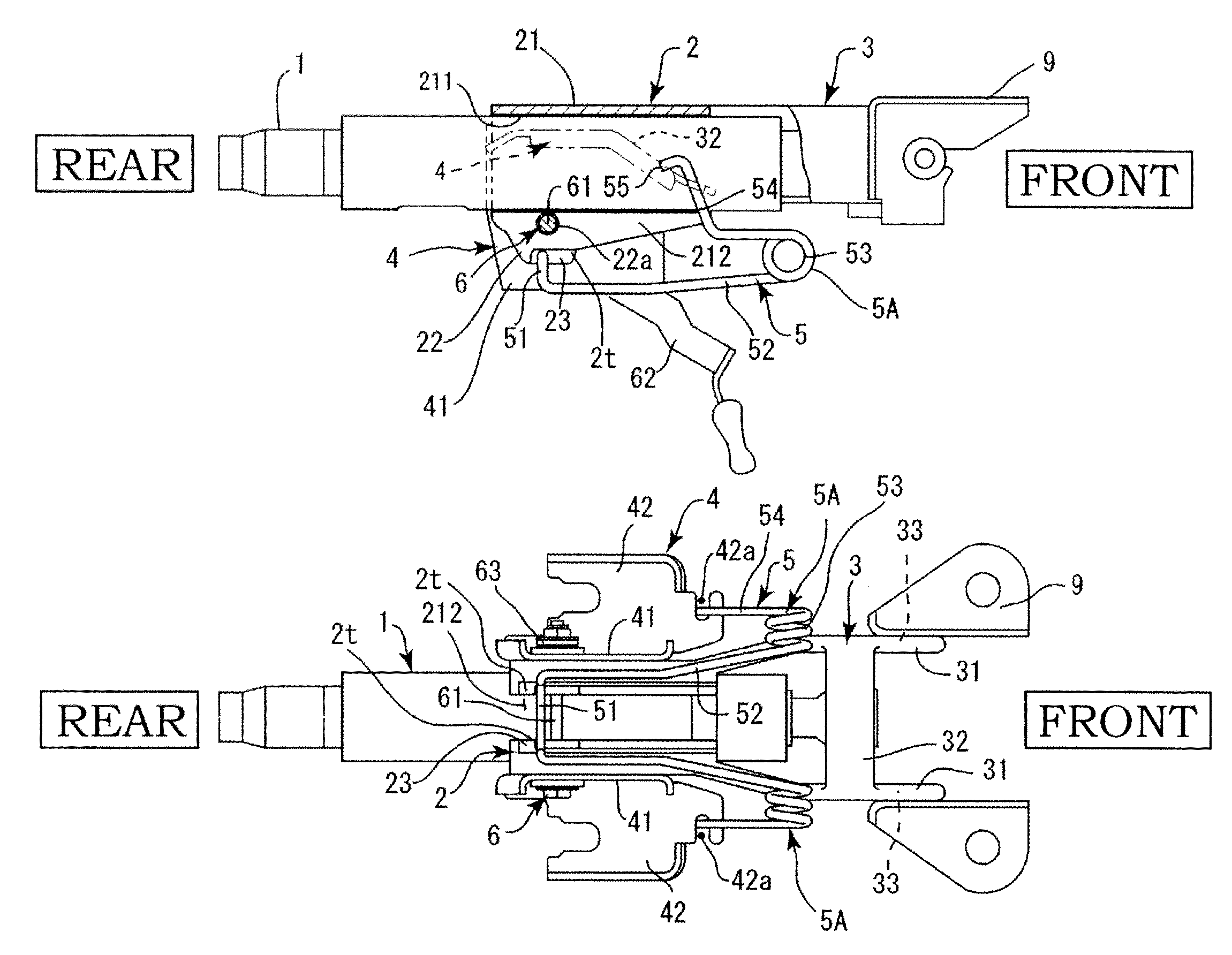
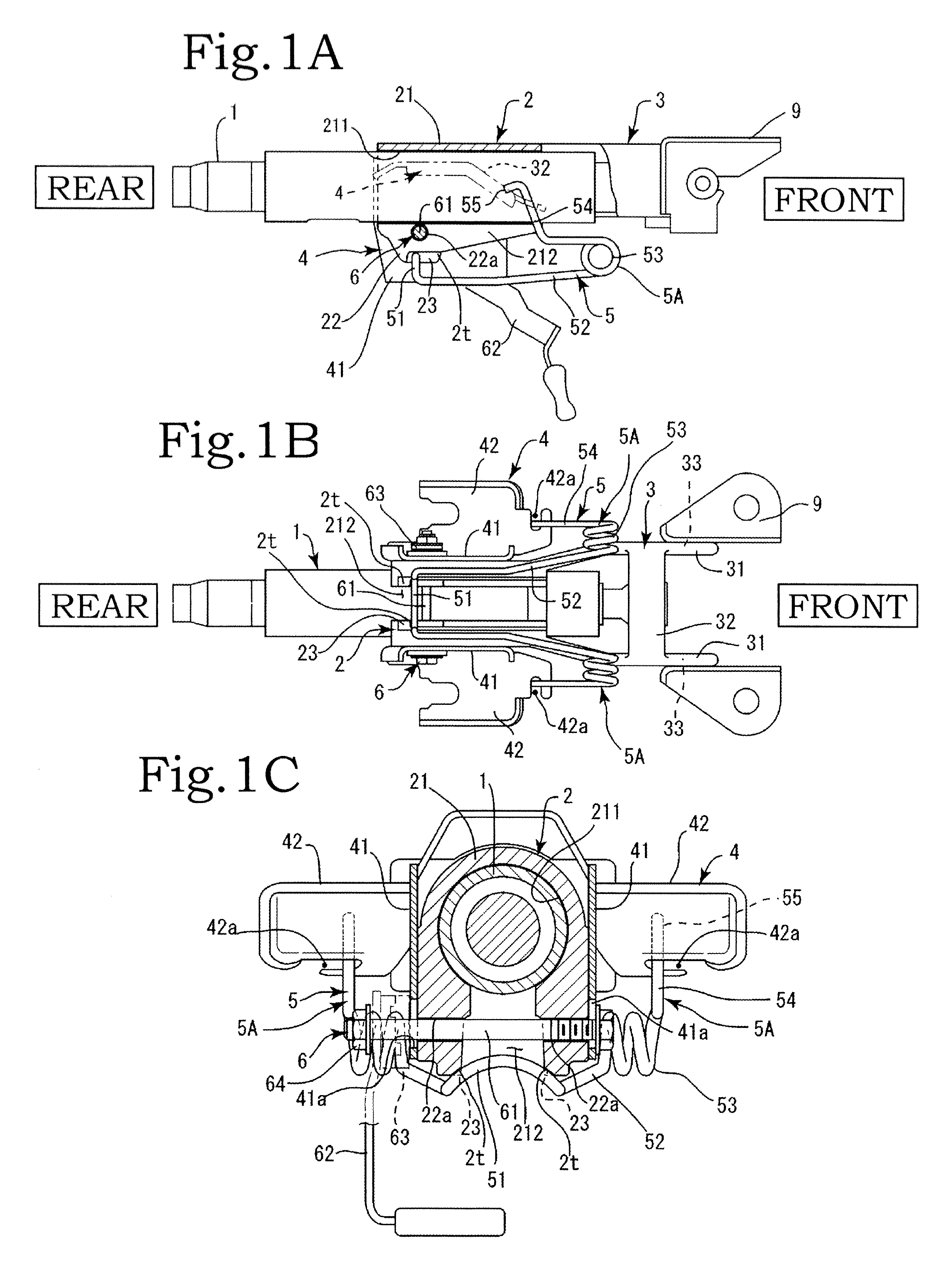
[0045]The pushing member can be implemented in a plurality of embodiments. In the first embodiment, as shown in FIGS. 3A and 3B, spring portions 5A are formed at both sides, in the width direction of the expanding shaft portion 51. The spring portion 5A serves as a means for elastically biasing the expanding shaft portion 51 upward.

[0046]In the spring portion 5A, first elastic shaft portions 52 are formed to extend rearward from the front side of the expanding shaft portion 51, return coil spring portions 53 are formed with a left-right symmetry at front axial ends of the two first elastic shaft portions 52, second elastic shaft portions 54 are formed rearward from the two return coil spring portions 53 toward the expanding shaft portion 51, and locking shaft portions 55 are formed to extend upward from the rear axial ends of the two second elastic shaft portions 54.

[0047]The expanding shaft portion 51 and the spring portion 5A are formed from a metal shaft material, and the expandi...

second embodiment

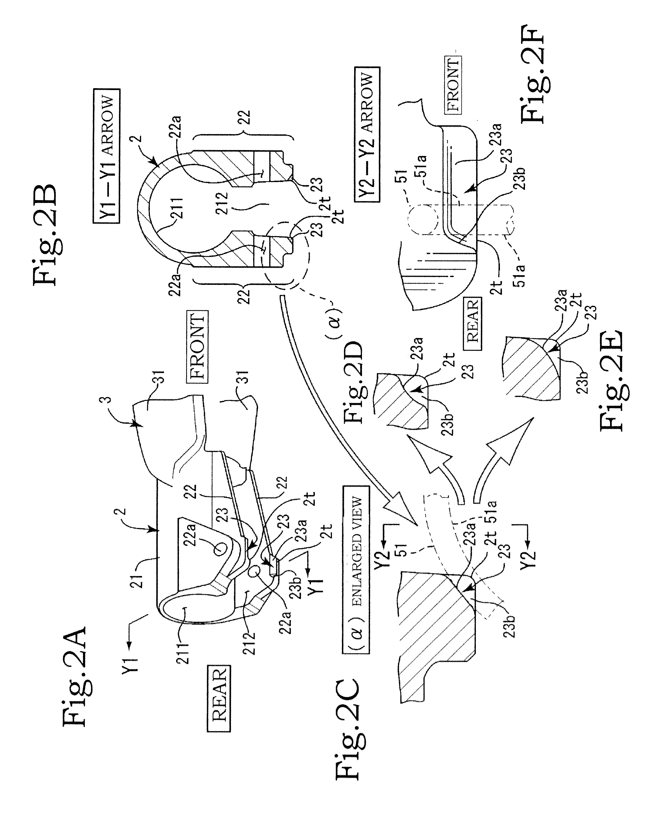
[0059]There is the pushing member 5. In this embodiment, as shown in FIG. 6A, the expanding shaft portion 51 and the spring portion 5A constituting the expansion are configured as separate members. As described hereinabove, the expanding shaft portion 51 has a shape with left-right symmetry in the width direction and has the inclined shaft pieces 51a symmetrical in the left-right direction. The two inclined shaft pieces 51a are formed as circular-arc peaks of a substantially semicircular shape, and a circular arc symmetrical in the left-right direction is constituted by the two inclined shaft pieces 51a.

[0060]There are also various modification examples of the expanding shaft portion 51 in the pushing member 5 of the second embodiment. Thus, the two inclined shaft pieces 51a can be formed as a peak of a substantially inverted “V”-like shape or triangular shape in the same manner as in the first embodiment, or a horizontal shaft piece 51b can be formed between the two inclined shaft...


PUM


Abstract

A steering device includes an outer column including fastening pieces formed to face each other at both sides, in the width direction, of a slot portion formed at either of a lower side or an upper side of an embracing body portion along an axial direction thereof, a fixed bracket clamping the outer column, a fastener that fastens the outer column and the fixed bracket, an inner column, and a pushing member having an expanding shaft portion. The two fastening pieces of the embracing body portion are connected by the fastener so that the two fastening pieces can be expanded and contracted, and the expanding shaft portion is elastically biased in an axial center direction of the outer column so as to abut on end zones of the slot portion and expand the two fastening pieces.

Description

BACKGROUND OF THE INVENTION[0001]1. Field of the Invention[0002]The present invention relates to a steering device in which when adjustment is performed in a telescopic adjustment mechanism, the release of fastening of an inner column by an outer column can be smoothly performed, whereby effective telescopic adjustment can be realized.[0003]2. Description of the Related Art[0004]A large number of steering devices equipped with a tilt-telescopic mechanism have been used. In particular, in manually operated devices, the outer column clamps the outer peripheral surface of the inner column from both sides in a substantially diametric direction, the clamping pressure is increased by a fastener constituted by a bolt shaft and an operation lever, and the inner column is strongly fixed to the outer column. Where the fastener is loosened, the clamping pressure is decreased, while the portion of the outer column that clamps the inner column is opened, the inner column can easily move in the a...

Claims


Application Information

Patent Timeline
IPC IPC(8): B62D1/187
CPCB62D1/189B62D1/184
Inventor TAKEZAWA, NAOYUKISATO, YOSHIYUKI
Owner YAMADA SEISAKUSHO KK
Why Eureka
Try Eureka