
Pick-up truck bed tool box system

Active Publication Date: 2012-08-09
VILLANO KENNETH J +1
View PDF3 Cites 21 Cited by
  • Summary
  • Abstract
  • Description
  • Claims
  • Application Information

AI Technical Summary

Benefits of technology

[0004]It is the object of the present invention to provide a pick-up truck bed tool box system which is easily and smoothly moveable between a stationary stored position on the floor of the bed of a pick-up truck to a position outside the truck, adjacent to its sidewall, to allow ready access to the toolbox.
[0005]It is another object of the present invention to provide a pick-up truck bed tool box system which is efficiently and economical to manufacture and install on a pick-up truck.
[0006]It is still another object of the present invention to provide a pick-up truck bed tool box system which is durable and reliable for providing prolonged operation and use.
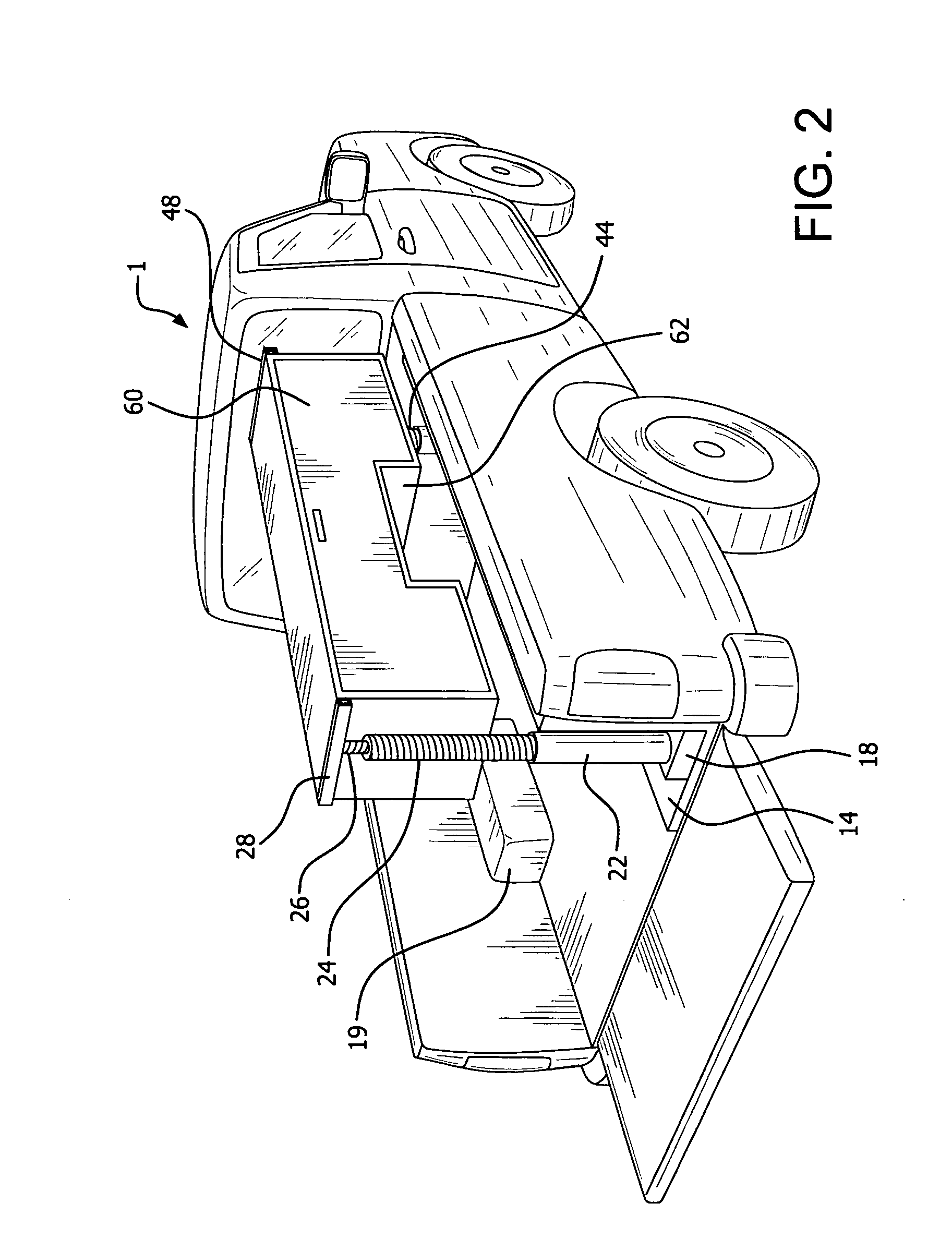
[0007]These and other objects are accomplished by the prevent invention, a pick-up truck bed toolbox system comprising a tool storage box which, in its stored, stationary position, rests on the floor of the bed of a pick-up truck such that it is parallel to the side wall of the truck. Electric motors, which can be remotely operated, are utilized to rotate dual, upstanding screw shafts which are connected via laterally extending cantilever arm members to the front and rear ends of the toolbox. The screw shafts raise the toolbox from its resting position on the floor of the bed of the pick-up truck, to an elevated position over the floor, and the shafts then operate to move the arm members laterally to extend the tool box to a position passed the side wall. The screw shafts can then be activated to lower the tool box to a lowered position outside the truck, adjacent to and alongside the sidewall, thus providing easy and ready access to the toolbox. The same system is utilized to return the toolbox from this lowered position outside the truck, to the floor of the truck bed.

Problems solved by technology

However, most of these systems, and others which have been suggested, are not generally incorporated into pick-up truck beds.
For instance, prior systems which have been proposed have never been reduced to actual practice since they do not work effectively or efficiently.
Many systems are subject to breakage with attendant costs of repair and others have components which are just too expensive to be economically practical.

Method used


Image

  • Pick-up truck bed tool box system
  • Pick-up truck bed tool box system
  • Pick-up truck bed tool box system

Examples


Embodiment Construction

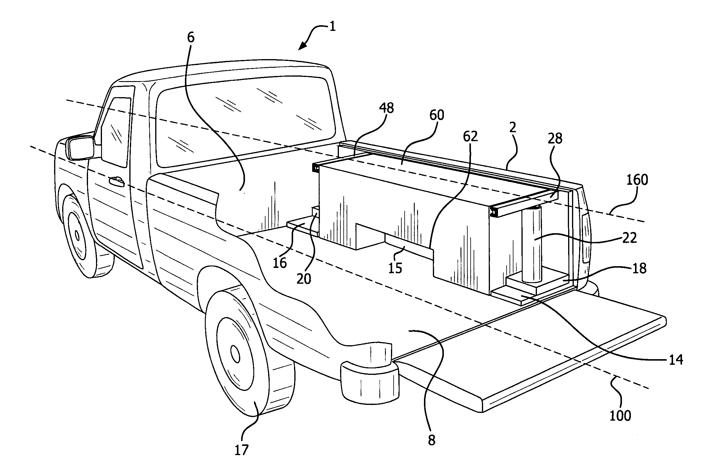
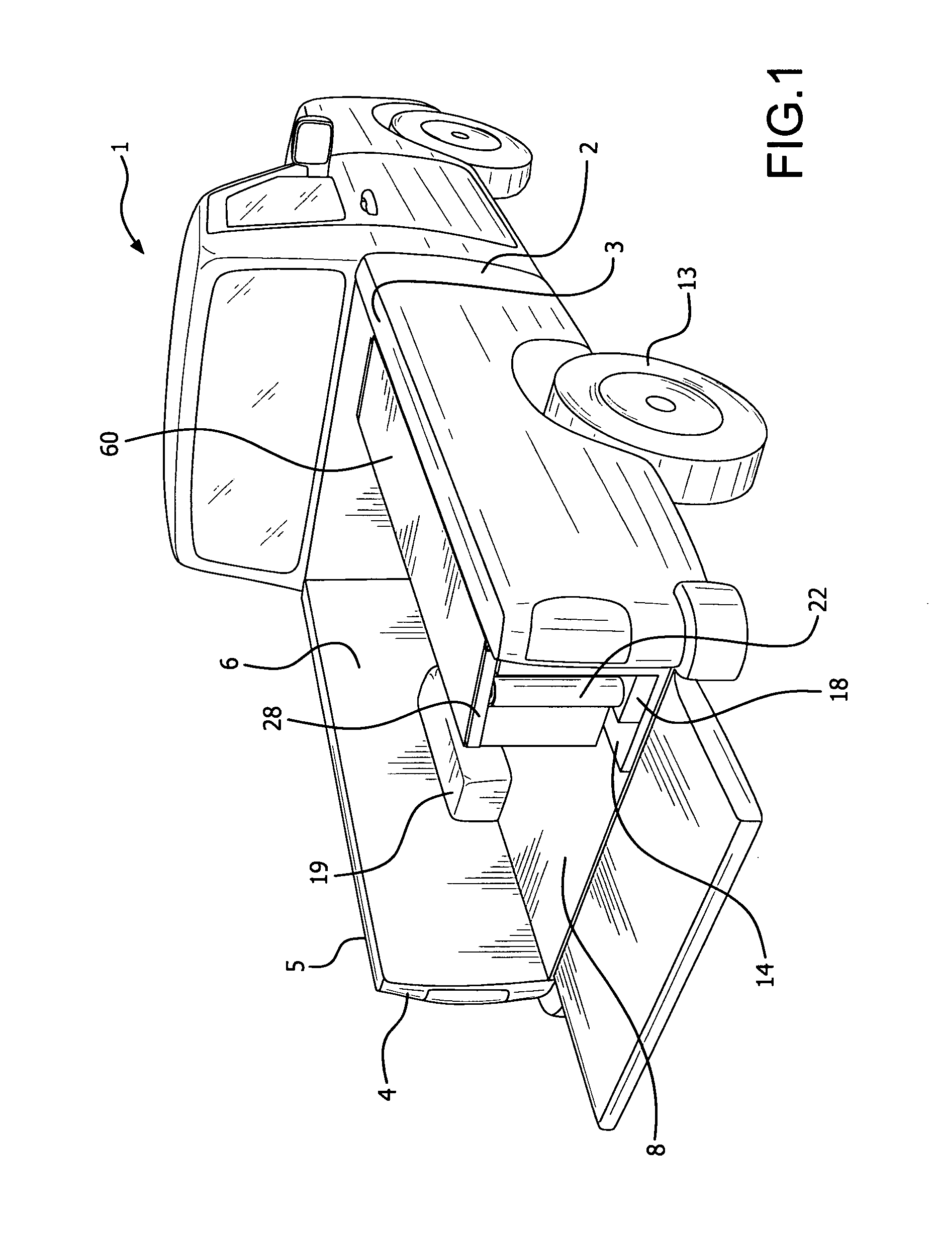
[0015]Pick-up truck 1 has longitudinal axis 100 and comprises sidewall 2 with top surface 3, sidewall 4 with top surface 5, and truck bed 6 having floor 8. Tire 13 extends into wheel well 15 and tire 17 extends into wheel well 19 of truck 1. Tool storage box 60 normally rests on or adjacent to truck floor 8 of truck bed 6; and, in this position, cutout opening 62 into the tool box accommodates wheel well 15.

[0016]Tool floor box system mounting unit 11, shown in detail in FIG. 6, comprises front section 12 and support pads 14 and 16, which are rigidly, screwed, bolted, welded or otherwise secured to floor 8. Mounting unit 11 is also secured to the inside surface of side wall 2. Motors 18 and 20, preferably electric, are secured in position on pads 14 and 16.

[0017]Vertical screw shaft casings 22 and 40 extend up from pads 14 and 16 respectively. Dual screw shafts 24 and 26 are rotatably housed within shaft casing 22, shaft 26 being connected through tool box lateral adjustment support...


PUM


Abstract

A pick-up truck bed toolbox system utilizes a tool storage box which, in its stored, stationary position, rests on the floor of the bed of a pick-up truck such that it is parallel to the side wall of the truck. Electric motors, which can be remotely operated, are utilized to rotate dual, upstanding screw shafts which are connected via laterally extending cantilever arm members to the front and rear ends of the toolbox. The screw shafts raise the toolbox from its resting position on the floor of the bed of the pick-up truck, to an elevated position over the floor, and the shafts then operate to move the arm members laterally to extend the tool box to a position passed the side wall. The screw shafts can then be activated to lower the tool box to a lowered position outside the truck, adjacent to and alongside the sidewall, thus providing easy and ready access to the toolbox. The same system is utilized to return the toolbox from this lowered position outside the truck, to the floor of the truck bed.

Description

FIELD OF THE INVENTION[0001]The present invention relates to toolboxes for the beds of pick-up trucks and, more particularly, to a motorized system for shifting a toolbox from the bed of a pick-up truck, to a position alongside the truck for ready access to the toolbox.BACKGROUND OF THE INVENTION[0002]It is common to position toolboxes, material and supplies, tool cabinets, and various other storage containers on the bed or on sidewalls of pick-up trucks, utility trailers or similar vehicles. While most such containers are immoveably fixed to the bed of a pick-up truck, there have been a number of proposed systems which move the toolbox within or out of the truck's bed. These proposed systems include mechanisms which slide or roll toolboxes to various locations within or out of the tool bed, support brackets to allow toolboxes to swing out of the bed, and devices which pivot toolboxes from positions within the bed. However, most of these systems, and others which have been suggested...

Claims


Application Information

Patent Timeline
IPC IPC(8): B60R11/06B60R9/00
CPCB60R11/06B60R9/065
Inventor VILLANO, KENNETH J.MORRIS, JOHN M.
Owner VILLANO KENNETH J
Learn More