
Dual band antenna

a dual-band antenna and antenna technology, applied in the direction of antennas, antenna details, elongated active element feed, etc., can solve the problems of large space required to accommodate low frequencies, increase the length of each element, and cannot be accommodated in the limited spa

Active Publication Date: 2012-08-09
LENOVO PC INT
View PDF11 Cites 16 Cited by
  • Summary
  • Abstract
  • Description
  • Claims
  • Application Information

AI Technical Summary

Problems solved by technology

Since the antenna increases in length as the resonance frequency decreases, a large space is required to accommodate low frequencies.
However, when the antenna structure of FIG. 6B is adopted for a new antenna to adapt the low-frequency side to the 700 MHz band, the length of each element increases, causing a problem that it cannot be accommodated in the limited space.
It is also necessary to mount multiple antennas in a small space in a laptop PC, and this may not be able to secure enough distance therebetween depending on the mounting condition.

Method used


Image

  • Dual band antenna
  • Dual band antenna
  • Dual band antenna

Examples


Embodiment Construction

[0024]It will be readily understood that the components of the embodiments, as generally described and illustrated in the figures herein, may be arranged and designed in a wide variety of different configurations in addition to the described example embodiments. Thus, the following more detailed description of the example embodiments, as represented in the figures, is not intended to limit the scope of the embodiments, as claimed, but is merely representative of example embodiments.

[0025]Reference throughout this specification to “one embodiment” or “an embodiment” (or the like) means that a particular feature, structure, or characteristic described in connection with the embodiment is included in at least one embodiment. Thus, appearances of the phrases “in one embodiment” or “in an embodiment” or the like in various places throughout this specification are not necessarily all referring to the same embodiment.

[0026]Furthermore, the described features, structures, or characteristics...


PUM


Abstract

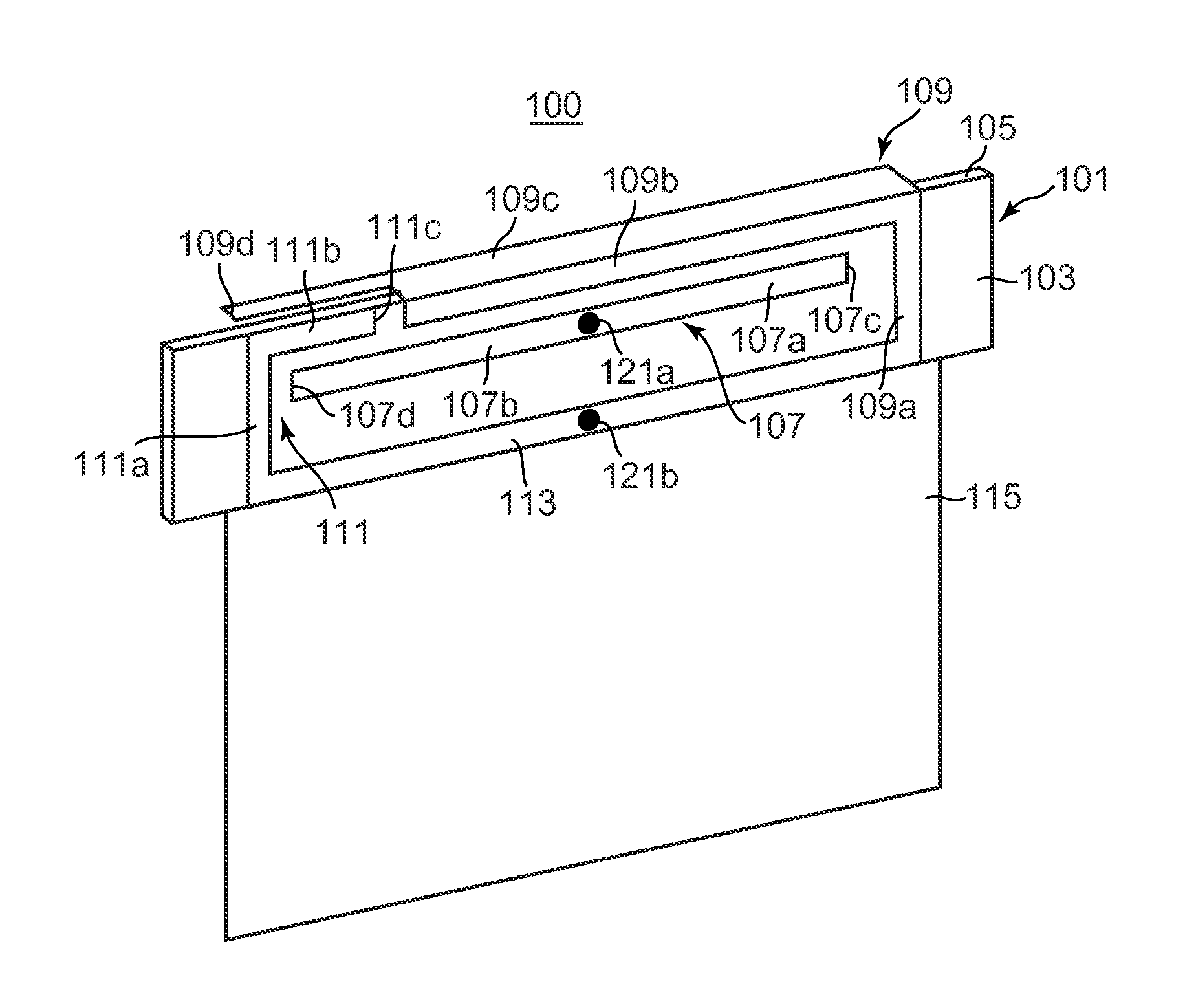
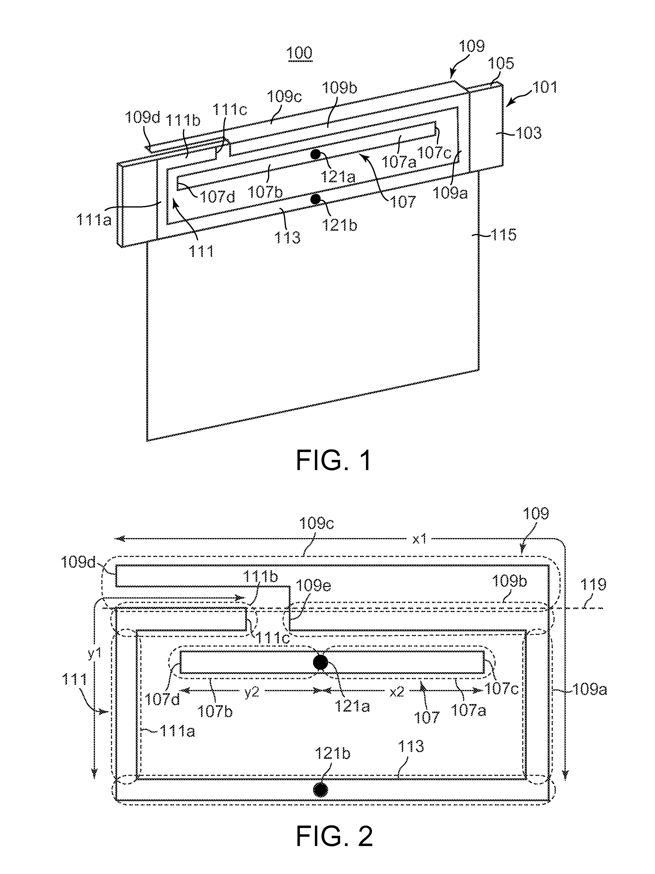
There is provided an apparatus comprising: a first radiation element having a horizontal pattern extending in parallel with a ground element and having a first open end; a second radiation element having a horizontal pattern extending in parallel with the ground element and having a second open end; wherein each of said first radiation element and second radiation element connects to the ground element; wherein said second open end of the second radiation element occupies an area surrounded by a horizontal pattern of the first radiation element and the ground element; and a driven element including a first excitation pattern extending along the horizontal pattern of the first radiation element and a second excitation pattern extending along the horizontal pattern of the second radiation element. Other embodiments are disclosed.

Description

CLAIM FOR PRIORITY[0001]This application claims priority from Japanese Application No. 2011-024597, filed on Feb. 8, 2011, and which is fully incorporated by reference as if fully set forth herein.FIELD OF THE INVENTION[0002]The subject matter described herein relates to a dual band antenna mountable in a wireless terminal.BACKGROUND[0003]There are frequencies for cellular phones in North America, namely the PCS (Personal Communications Service) band and the cellular band. In the PCS band, a frequency band from 1700 MHz to 2200 MHz is used as the 2 GHz band. In the cellular band, a frequency band from 820 MHz to 960 MHz has been previously used as the 800 MHz band, and recently, a mobile telecommunications service based on a communication standard called LTE (Long Term Evolution) has started as the 700 MHz band in the cellular band.[0004]In the United States, Verizon Wireless Inc. and AT&T Inc. offer wireless data communication services using LTE. Verizon Wireless Inc. uses a freque...

Claims


Application Information

Patent Timeline
IPC IPC(8): H01Q5/01H01Q5/10
CPCH01Q9/42H01Q5/371H01Q1/243
Inventor LEE, SUNGGYOO
Owner LENOVO PC INT
Learn More