
Diaphragm control apparatus of interchangeable lens camera

Active Publication Date: 2010-12-30
PENTAX RICOH IMAGING CO LTD
View PDF8 Cites 10 Cited by
  • Summary
  • Abstract
  • Description
  • Claims
  • Application Information

AI Technical Summary

Benefits of technology

[0009]The present invention has been devised in view of the above described problems of the prior art and provides a diaphragm control apparatus of an interchangeable lens camera, wherein the diaphragm control apparatus makes it possible to perform continuous diaphragm control during exposure even if an interchangeable lens that is equipped with a diaphragm operatively-associated rod is attached to the camera body, and further makes it possible to perform precise stepping-drive control for the diaphragm even if a stepping motor is used as a driving source of the diaphragm control apparatus.
[0017]This control makes it possible to detect the position of the slider in a linear detection characteristic range of the position detector, thus making it possible to perform the arithmetic operation with higher precision.

Problems solved by technology

As a result, the stepping motor (the rotor thereof) rotates from the initial detent position thereof, making the stop position of the stepping motor uncertain.
Additionally, in conventional interchangeable lenses, it is sometimes the case that the open-aperture reference position of the diaphragm operatively-associated rod, i.e., the initial position thereof relative to a camera body when an interchangeable lens is attached to the camera body, may be erroneous due to mechanical error or assembling error, etc.
In such a case also, due to this positional error, it is sometimes the case that the stop position of the stepping motor deviates from the preset initial position thereof.
In this type of stepping motor, if the stop position and the phase of the excitation pattern do not coincide with each other, a problem occurs with the stepping motor possibly rotating in a direction reverse to the required rotational direction, or even not rotating at all, which causes a mismatch between the number of excitations and the number of steps for driving the stepping motor, thus causing an error in f-number control.
In the case of bringing the stepping motor into a free state by cutting off the power applied to the stepping motor after driving the stepping motor stepwise until the motion of the diaphragm control mechanism is mechanically restricted to detect the initial excitation pattern of the stop position (herein referred as the “origin position”) of the stepping motor, there is a possibility of the stop position of the stepping motor becoming unstable upon the stepping motor entering a free state because, e.g., some components of the diaphragm control mechanism may be deformed by the torque and the inertial force of the stepping motor, and the restoring force of such elements may force the stepping motor to rotate in reverse upon the stepping motor entering a free state.

Method used


Image

  • Diaphragm control apparatus of interchangeable lens camera
  • Diaphragm control apparatus of interchangeable lens camera
  • Diaphragm control apparatus of interchangeable lens camera

Examples


Embodiment Construction

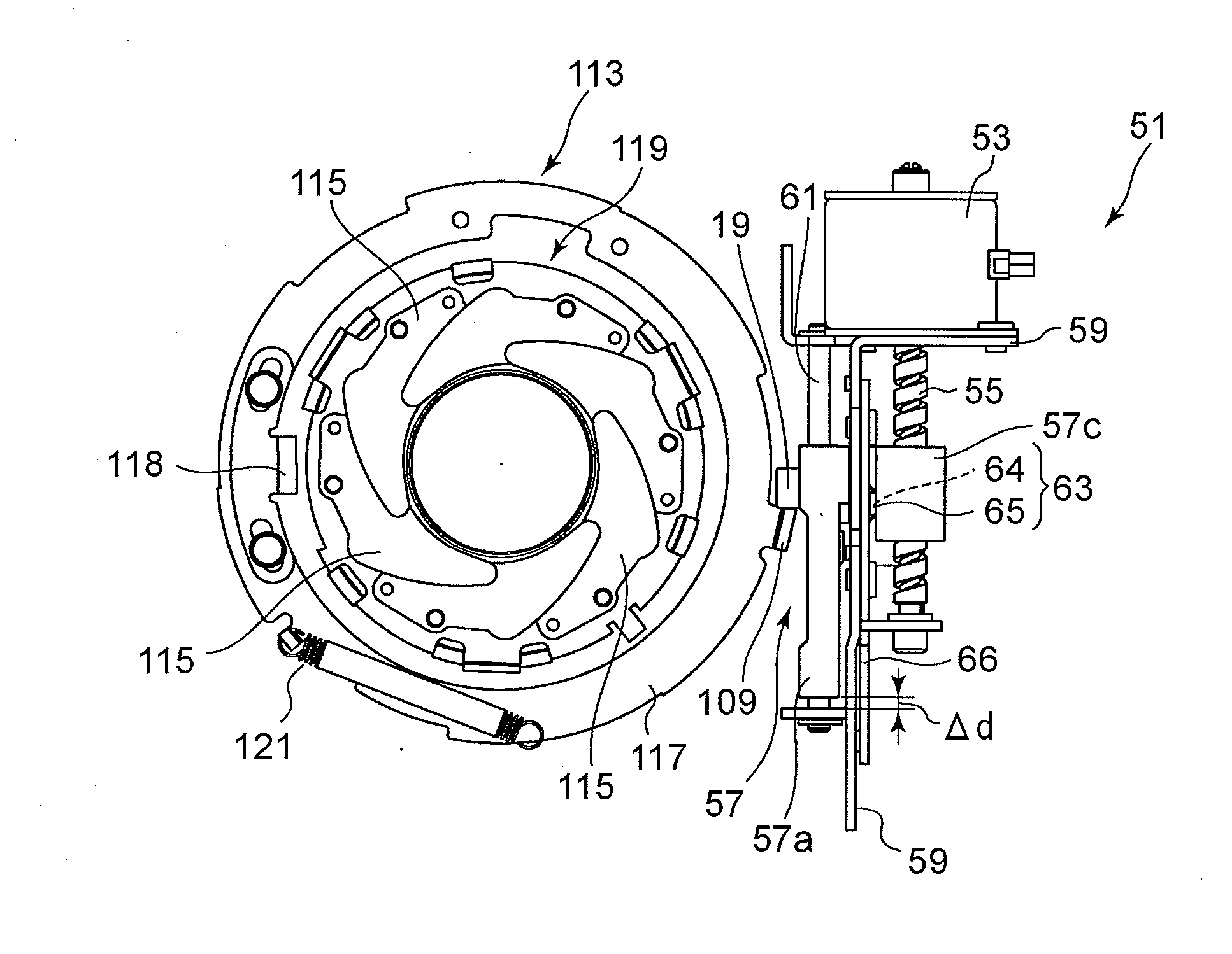
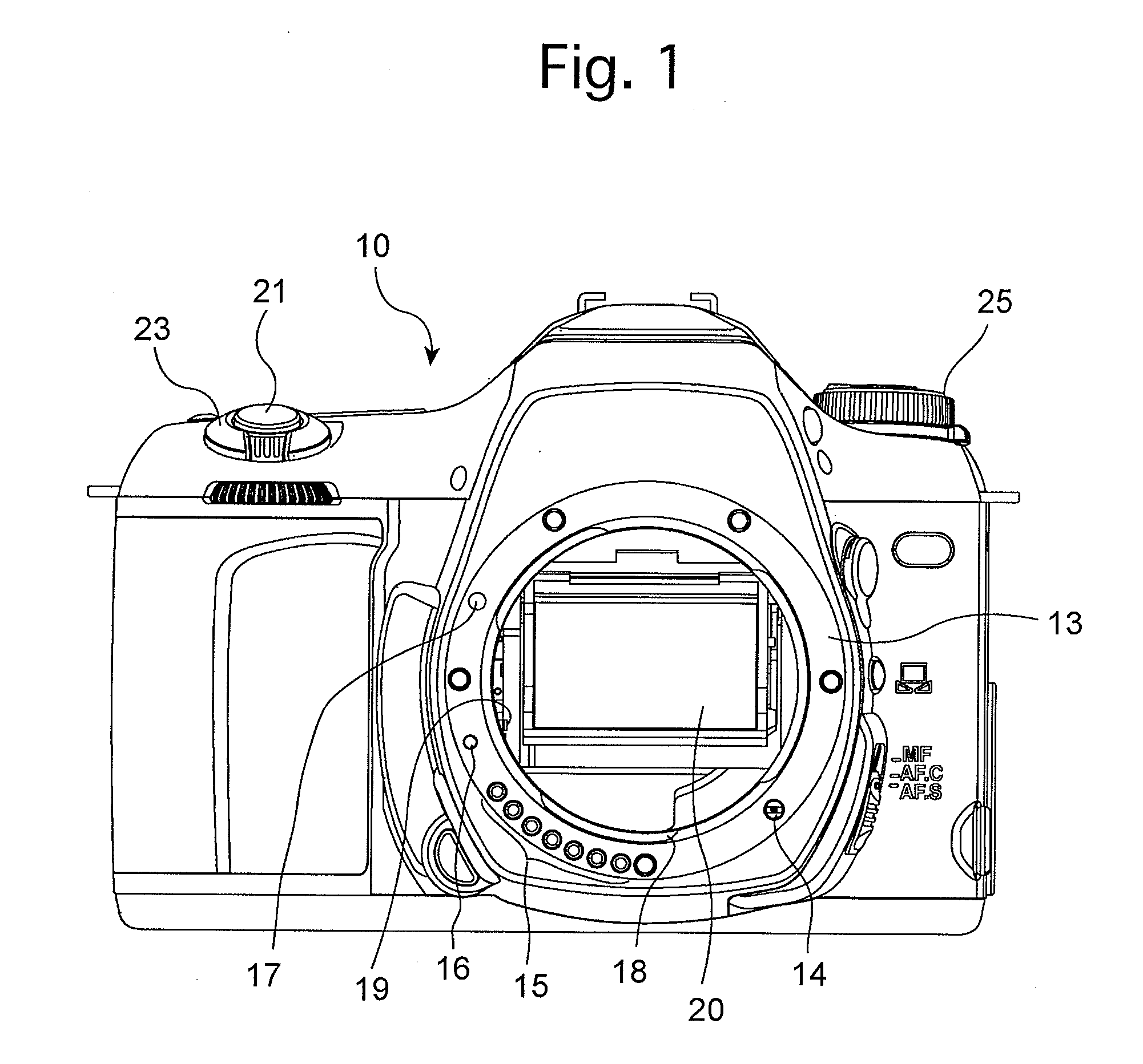
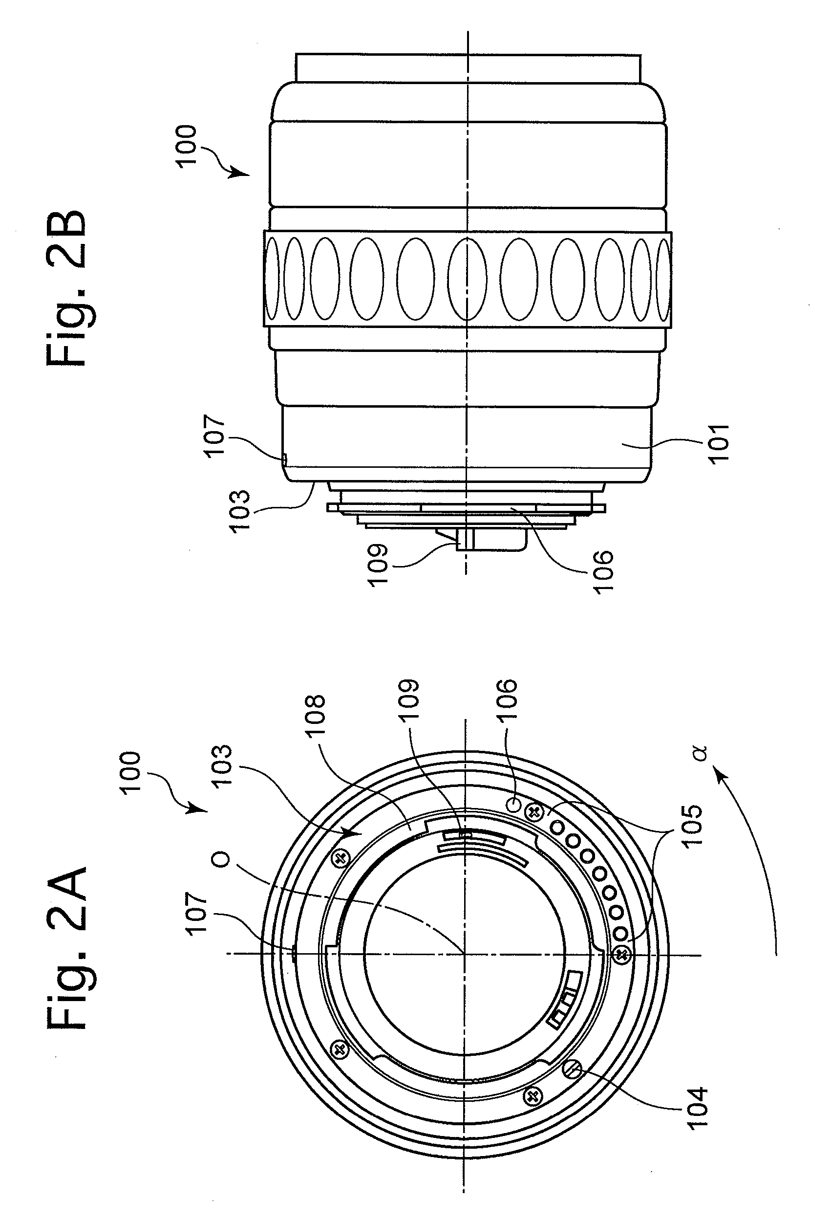
[0044]An embodiment of an SLR camera system according to the present invention is provided with a camera body 10 and an interchangeable lens (photographic lens) 100 that is detachably attached to the camera body 10. A body mount (mount ring) 13 is fixed to an approximate center of the front of the camera body 10. The camera body 10 is provided on the surface of the body mount 13 with an AF coupler 14, a group of information contacts 15, a lock pin 16 and amount index mark 17. The camera body 10 is provided on an inner periphery of the body mount 13 with a bayonet mount 18. The camera body 10 is provided in a mirror box thereof with a main mirror 20, and is provided, on the left hand side of the main mirror 20 with respect to FIG. 1 in the vicinity of the bayonet mount 18, with a diaphragm control rod 19 for controlling movements of a diaphragm operatively-associated rod 109 of the interchangeable lens 100 (see FIGS. 2A and 2B).

[0045]The camera body 10 is provided, on the top left th...


PUM


Abstract

A diaphragm control apparatus is provided in a camera body, in which a controller drives a stepping motor to move the slider away from an origin position, thereafter drives the stepping motor in the opposite direction toward the origin position, and thereafter detects the slider position after holding the stepping motor for a first waiting time upon a distance from the slider to the origin position becoming less than slider-moving distance for one step of the stepping motor. The controller causes the stepping motor to enter a free state upon a lapse of the first waiting time and detects the slider position upon a lapse of a second waiting time to set an initial excitation pattern from a difference between the slider position detected during the first waiting time and the slider position detected in the free state thereof and from the moving distance of the slider.

Description

BACKGROUND OF THE INVENTION[0001]1. Field of the Invention[0002]The present invention relates to a diaphragm control apparatus of an interchangeable lens camera, and in particular, relates to a diaphragm control apparatus which enables an adjustable diaphragm of an interchangeable lens (attached to a camera body) to be controlled by the camera body during exposure in an interchangeable lens SLR camera system.[0003]2. Description of the Related Art[0004]Diaphragm mechanisms (i.e., aperture mechanisms) of conventional interchangeable lens SLR camera systems are configured in a manner so that a diaphragm control bar, which constitutes an element of a diaphragm control mechanism of a camera body, moves a diaphragm operatively-associated rod of the interchangeable lens that is provided to drive a diaphragm mechanism of the interchangeable lens. In the case where the diaphragm control mechanism is powered by a motor of a mirror drive mechanism or a shutter charge mechanism, the diaphragm ...

Claims


Application Information

Patent Timeline
IPC IPC(8): G03B7/10
CPCG03B7/10
Inventor YAMADA, TOSHIAKISANADA, SHINICHIROKOSAKO, KOSEIOHSAWA, YUTAKAUENO, HIROTAKA
Owner PENTAX RICOH IMAGING CO LTD
Learn More