Head and arm detection for virtual immersion systems and methods

a technology of virtual immersion and head and arm detection, applied in the field of display of virtual environments, can solve the problems of inherently problematic interactions between physical environment/objects and virtual content, image quality, aesthetic continuity, etc., and achieve the effect of improving quality

Inactive Publication Date: 2012-08-09
EXPERIENCE PROXIMITY
View PDF6 Cites 75 Cited by
  • Summary
  • Abstract
  • Description
  • Claims
  • Application Information

AI Technical Summary

Benefits of technology

[0016]In various embodiments, the multiple sensors used to determine the user's proximity, position and / or viewpoint relative to the display may be used to create regions of increasing immersion on a display based on the user's position, proximity or viewpoint. Additionally, with the use of two or more sensors in concert over use of a single sensor, some embodiments can: observe users around the display in greater detail (e.g., tracking body, arm, head and leg position in addition to tracking the user's face), receive higher quality sensor data (e.g., interpolate between data from multiple sensors), or provide sensor redundancy in the event that one or more of the multiple sensors ceases to operate properly (e.g., when face tracking camera fails, a position sensor can be used to detect a user's head position).

Problems solved by technology

Unfortunately, the process of adding computer images or CGI to “real world” objects often appears unrealistic and creates problems of image quality, aesthetic continuity, temporal synchronization, spatial registration, focus continuity, occlusions, obstructions, collisions, reflections, shadows and refraction.
Interactions (collisions, reflections, interacting shadows, light refraction) between the physical environment / objects and virtual content is inherently problematic due to the fact the virtual content and the physical environment does not co-exist in the same space but rather they only appear to co-exist.
For example, an animated object depicted on a transparent display may not be able to interact with the environment seen through the display.
If the animated object does interact with the “real world” environment, then a part of that “real world” environment must also be animated and creates additional problems in synchronizing with the rest of the “real world” environment.
Transparent mixed reality displays that overlay virtual content onto the physical world suffer from the fact that the virtual content is rendered onto a display surface that is not located at the same position as the physical environment or object that is visible through the screen.
This switching of focus produces an uncomfortable experience for the observer.

Method used


Image

  • Head and arm detection for virtual immersion systems and methods
  • Head and arm detection for virtual immersion systems and methods
  • Head and arm detection for virtual immersion systems and methods

Examples


Embodiment Construction

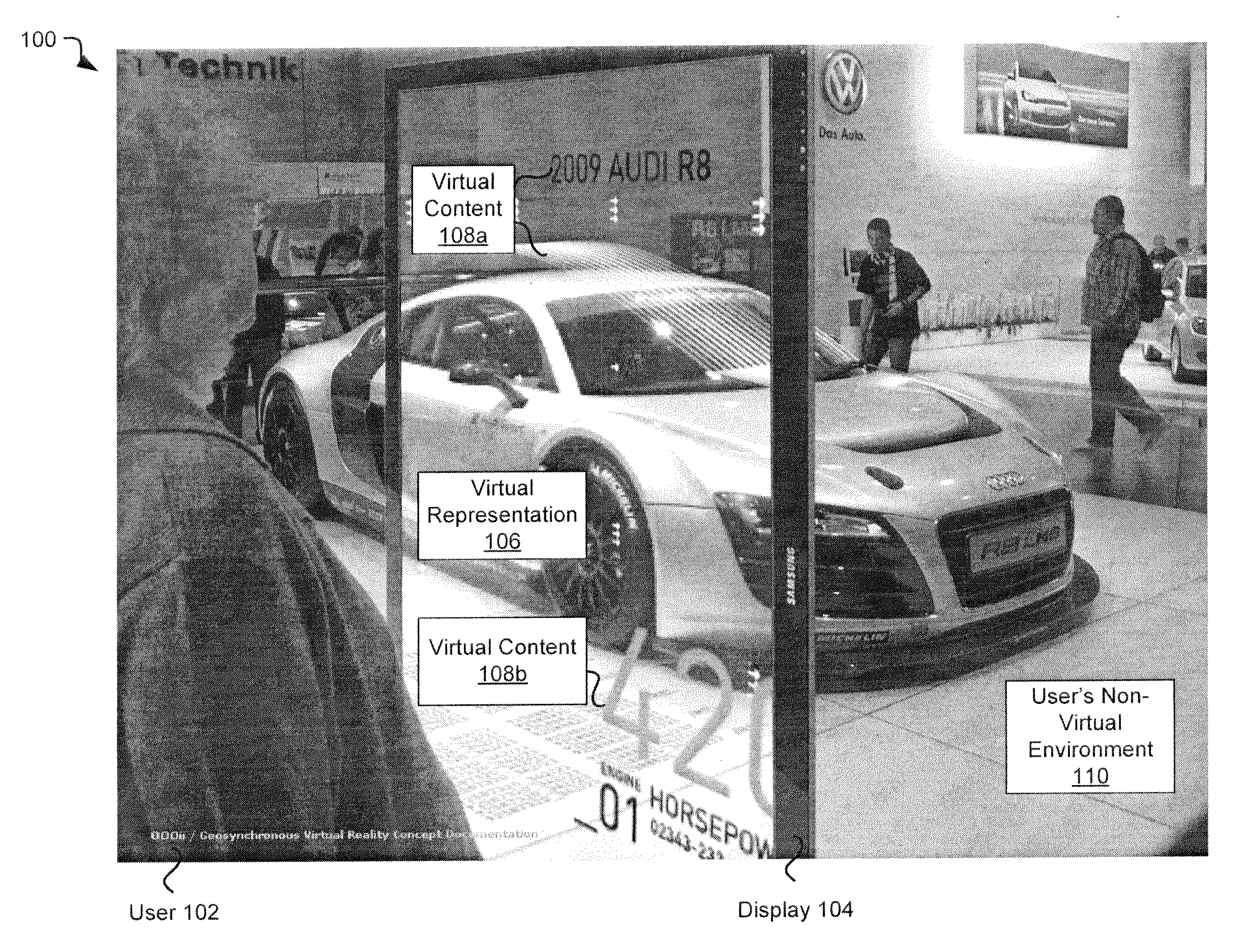
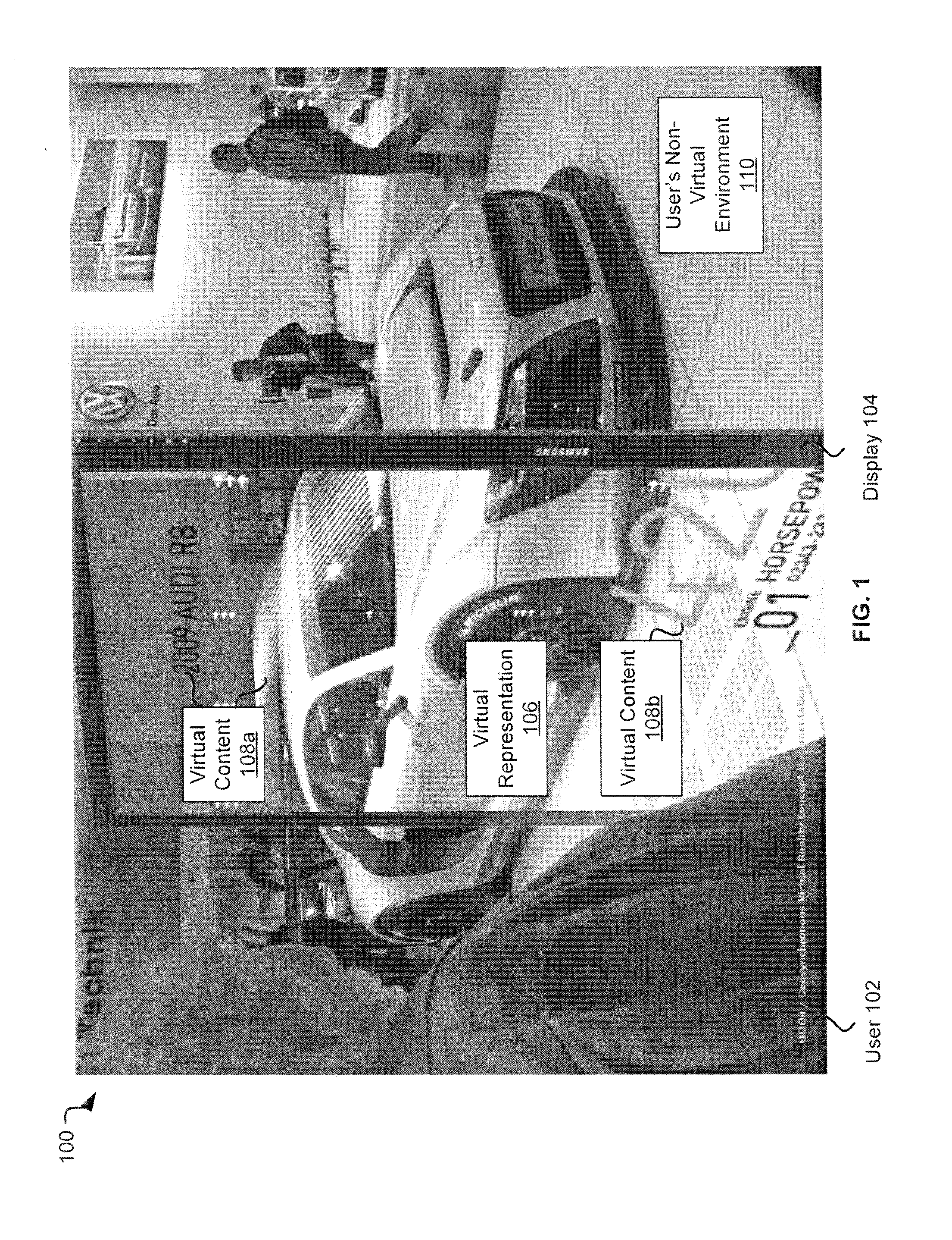
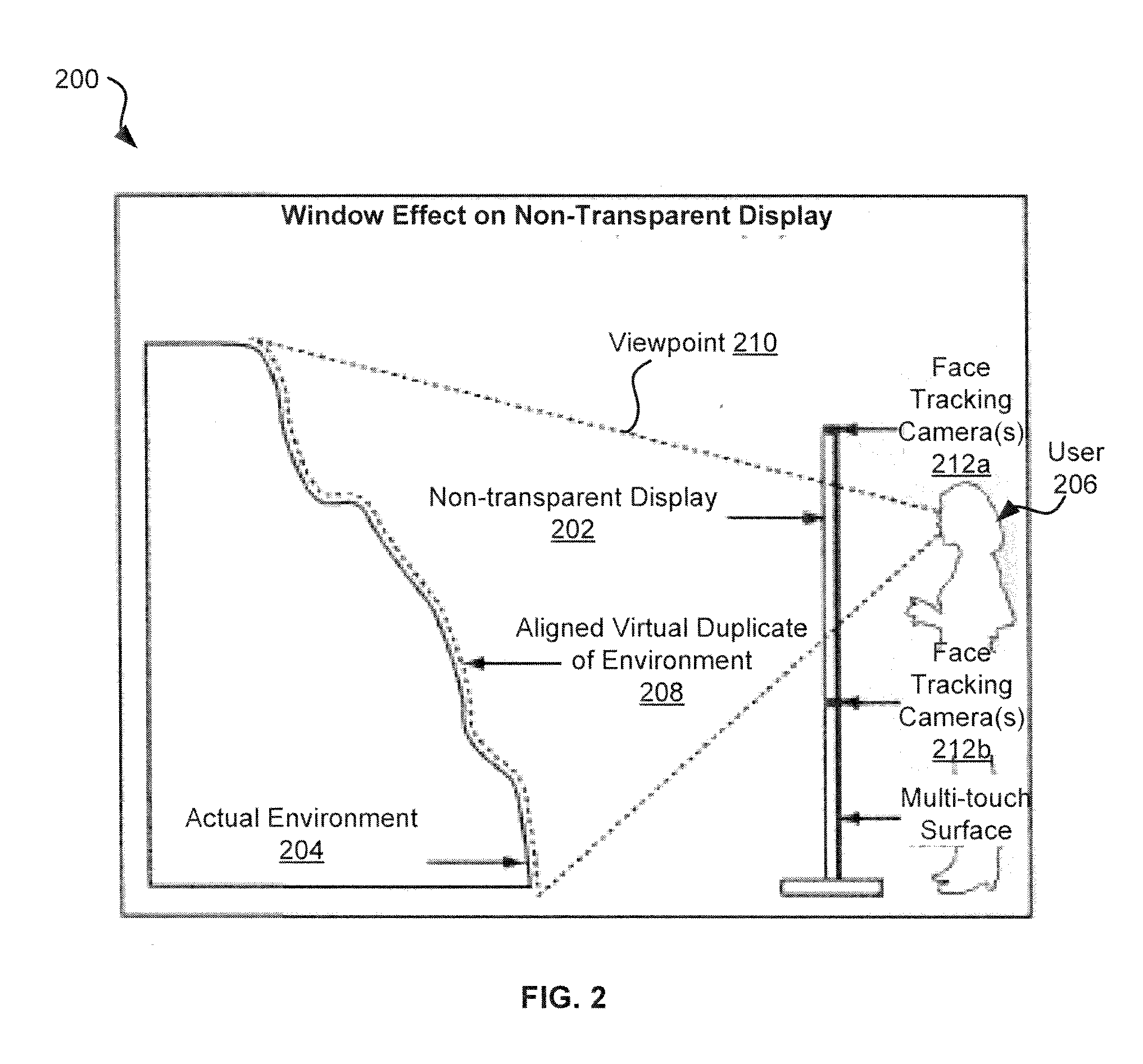
[0042]Exemplary systems and methods described herein allow for user interaction with a virtual environment. In various embodiments, a display may be placed within a user's non-virtual environment. The display may depict a virtual representation of at least a part of the user's non-virtual environment. The virtual representation may be spatially aligned with the user's non-virtual environment such that the user may perceive the virtual representation as being a part of the user's non-virtual environment. For example, the user may see the display as a window through which the user may perceive the non-virtual environment on the other side of the display. The user may also view and / or interact with virtual content depicted by the display that is not a part of the non-virtual environment. As a result, the user may interact with an immersive virtual reality that extends and / or augments the non-virtual environment.

[0043]In one exemplary system, a virtual representation of a physical space...


PUM


Abstract

Systems and methods for detection of the head and arms of a user to interact with an immersive virtual environment are disclosed. In some embodiments, a method comprises generating a virtual representation of a non-virtual environment, determining a position of a user relative to the display using an overhead sensor when the user is within a predetermined proximity to a display, determining a position of a user's head relative to the display using the overhead sensor, and displaying the virtual representation on the display in a spatial relationship with the non-virtual environment based on the position of the user's head relative to the display.

Description

CROSS-REFERENCE TO RELATED APPLICATION[0001]The present application claims benefit of and seeks priority to U.S. Provisional Patent Application No. 61 / 389,681, filed Oct. 4, 2010, entitled “Depth-Sensing Camera from Above” which is incorporated by reference herein. The present application is also a continuation-in-part of U.S. patent application Ser. No. 13 / 207,312, filed Aug. 20, 2011, entitled Multi-Sensor Proximity-Based Immersion System and Method” which is a continuation-in-part of and claims benefit of U.S. patent application Ser. No. 12 / 823,089 filed Jun. 24, 2010, entitled “Systems and Methods for Interaction with a Virtual Environment,” which claims the benefit of the similarly entitled U.S. Provisional Patent Application No. 61 / 357,930 filed Jun. 23, 2010, each of which is incorporated by reference. The U.S. patent application Ser. No. 13 / 207,312 also claimed the benefit of U.S. Provisional Patent Application No. 61 / 372,838 filed Aug. 11, 2010, entitled “Multi-sensor Proxi...

Claims


Application Information

Patent Timeline
Patent Type & Authority Applications(United States)
IPC IPC(8): G09G5/00G06F3/033
CPCA63F13/10A63F2300/302G06F3/012G06F3/04883G06T19/00A63F2300/69A63F2300/1093A63F2300/203A63F2300/308A63F2300/6045G06T19/006A63F13/42A63F13/213
Inventor DEMAINE, KENT
Owner EXPERIENCE PROXIMITY
Why Eureka
Try Eureka