User friendly interface for control unit

a control unit and user-friendly technology, applied in the direction of instruments, heating types, static/dynamic balance measurement, etc., can solve problems such as blockage of hvac operation

Active Publication Date: 2012-08-09
GOOGLE LLC
View PDF28 Cites 289 Cited by
  • Summary
  • Abstract
  • Description
  • Claims
  • Application Information

AI Technical Summary

Benefits of technology

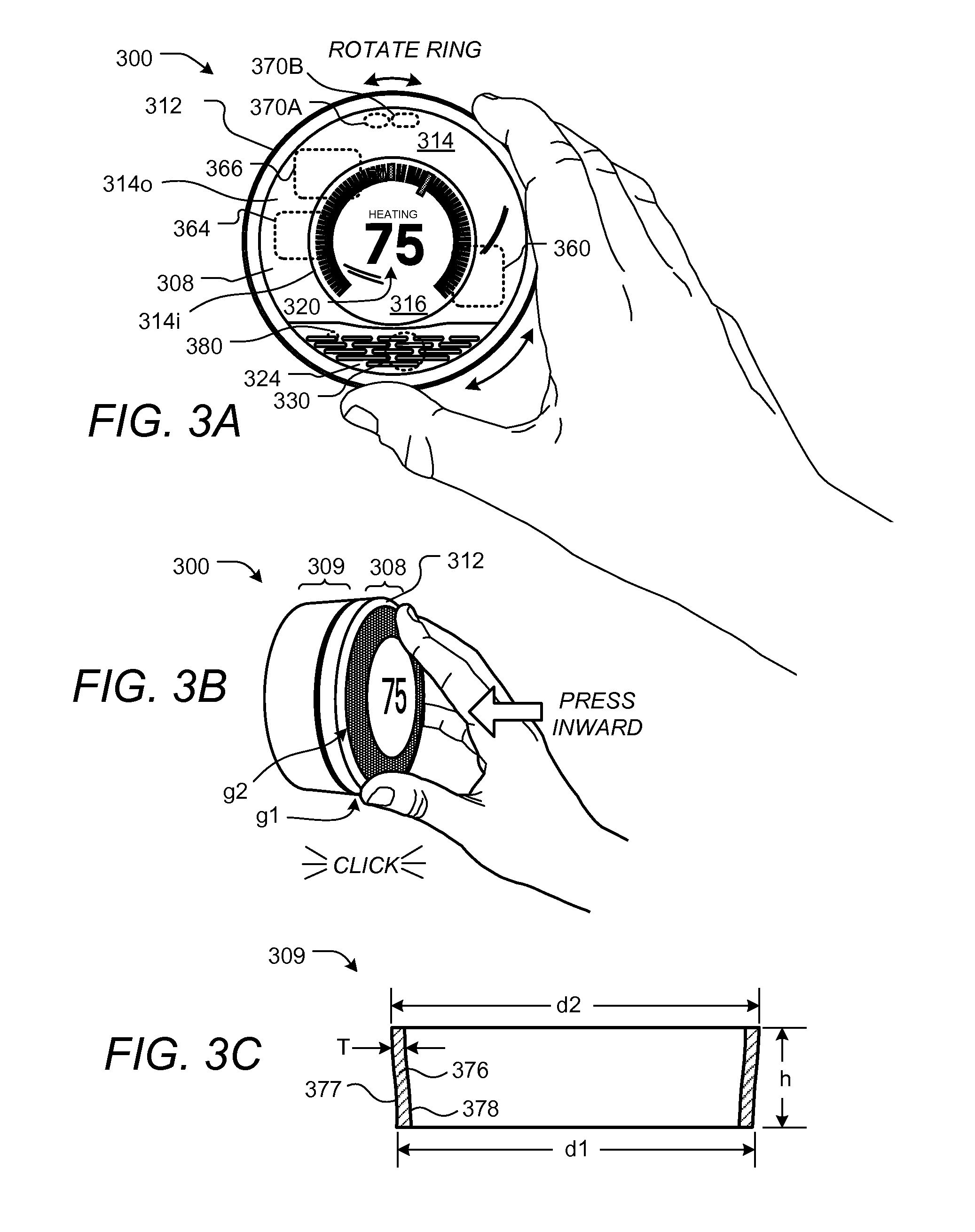
[0008]Provided according to one or more embodiments is a user interface for a programmable device, such as a programmable thermostat, that controls the operation of one or more energy-consuming systems, household devices, or other resource-consuming systems, such as a heating, ventilation, and air conditioning (HVAC) system. Further provided are systems, methods, computer program products, and related business methods associated with the user interface and programmable device. For some embodiments, the programmable device is configured to carry out a method for interacting with a user thereof, the method comprising displaying a plurality of background tick marks arcuately arranged within a range area on a rounded display that is centrally mounted on a rounded body of the programmable device. A setpoint tick mark is displayed on the rounded display within the range area such that the setpoint tick mark is more prominently visible to the user than the background tick marks, the setpoint tick mark representing a setpoint temperature. Numerical representations of the current temperature and the setpoint temperature are displayed on the rounded display, and input representing a desired change in the setpoint temperature is received from the user by user rotation of a rotatable ring surrounding the rounded display. The setpoint tick mark is moved in response to and in accordance with the received input such that the change in setpoint is visible to the user.

Problems solved by technology

However, some wiring errors are serious enough such that HVAC operation is blocked.

Method used


Image

  • User friendly interface for control unit
  • User friendly interface for control unit
  • User friendly interface for control unit

Examples


Embodiment Construction

[0031]A detailed description of the inventive body of work is provided below. While several embodiments are described, it should be understood that the inventive body of work is not limited to any one embodiment, but instead encompasses numerous alternatives, modifications, and equivalents. In addition, while numerous specific details are set forth in the following description in order to provide a thorough understanding of the inventive body of work, some embodiments can be practiced without some or all of these details. Moreover, for the purpose of clarity, certain technical material that is known in the related art has not been described in detail in order to avoid unnecessarily obscuring the inventive body of work.

[0032]As used herein the term “HVAC” includes systems providing both heating and cooling, heating only, cooling only, as well as systems that provide other occupant comfort and / or conditioning functionality such as humidification, dehumidification and ventilation.

[0033...


PUM


Abstract

A user-friendly programmable thermostat is described that includes a central electronic display surrounded by a ring that can be rotated and pressed inwardly to provide user input in a simple and elegant fashion. The current temperature and setpoint are graphically displayed as prominent tick marks. Different colors and intensities can be displayed to indicate currently active HVAC functions and an amount of heating or cooling required to reach a target temperature. The setpoint can be altered by user rotation of the ring. The schedule can be displayed and altered by virtue of rotations and inward pressings of the ring. Initial device set up and installation, the viewing of device operation, the editing of various settings, and the viewing of historical energy usage information are made simple and elegant by virtue of the described form factor, display modalities, and user input modalities of the device.

Description

CROSS-REFERENCE TO RELATED APPLICATIONS[0001]This patent is a continuation-in-part of U.S. Ser. No. 13 / 033,573, filed Feb. 23, 2011. This patent application also claims the benefit of U.S. Prov. Ser. No. 61 / 415,771 filed Nov. 19, 2010; and of U.S. Prov. Ser. No. 61 / 429,093 filed Dec. 31, 2010, each of which is incorporated by reference herein. The subject matter of this patent specification also relates to the subject matter of the following commonly assigned applications: U.S. Ser. No. 12 / 881,430 filed Sep. 14, 2010; U.S. Ser. No. 12 / 881,463 filed Sep. 14, 2010; U.S. Ser. No. 12 / 984,602 filed Jan. 4, 2011; U.S. Ser. No. 12 / 987,257 filed Jan. 10, 2011; U.S. Ser. No. 13 / 033,573 and US. Ser. No. 29 / 386,021, filed Feb. 23, 2011; U.S. Ser. No. 13 / 034,666, U.S. Ser. No. 13 / 034,674 and U.S. Ser. No. 13 / 034,678 filed Feb. 24, 2011; U.S. Ser. No. 13 / 038,206 and U.S. Ser. No. 13 / 038,191 filed Mar. 1, 2011; U.S. Ser. No. 29 / 399,609 filed Aug. 16, 2011; U.S. Ser. No. 29 / 399,614 filed Aug. 16, ...

Claims


Application Information

Patent Timeline
Patent Type & Authority Applications(United States)
IPC IPC(8): G05D23/19
CPCF24F11/0086F24F2011/0091F24F2221/32G06F3/04847G05D23/19G05D23/1917G06F3/0482G05D23/1902G06K7/146G06K7/1465F24F11/52F24F11/30
Inventor SLOO, DAVIDFADELL, ANTHONY MICHAELROGERS, MATTHEW LEEPLITKINS, MICHAELMATAS, MICHAEL JAMESBOULD, FRED
Owner GOOGLE LLC
Why Eureka
Try Eureka