Turbine tip clearance measurement

Active Publication Date: 2012-08-16
SIEMENS ENERGY INC
View PDF5 Cites 39 Cited by
  • Summary
  • Abstract
  • Description
  • Claims
  • Application Information

AI Technical Summary

Problems solved by technology

It is desirable to keep the clearance as small as possible to increase engine performance because fluid leak

Method used


Image

  • Turbine tip clearance measurement
  • Turbine tip clearance measurement
  • Turbine tip clearance measurement

Examples


Embodiment Construction

[0016]In the following detailed description of the preferred embodiment, reference is made to the accompanying drawings that form a part hereof, and in which is shown by way of illustration, and not by way of limitation, specific preferred embodiments in which the invention may be practiced. It is to be understood that other embodiments may be utilized and that changes may be made without departing from the spirit and scope of the present invention.

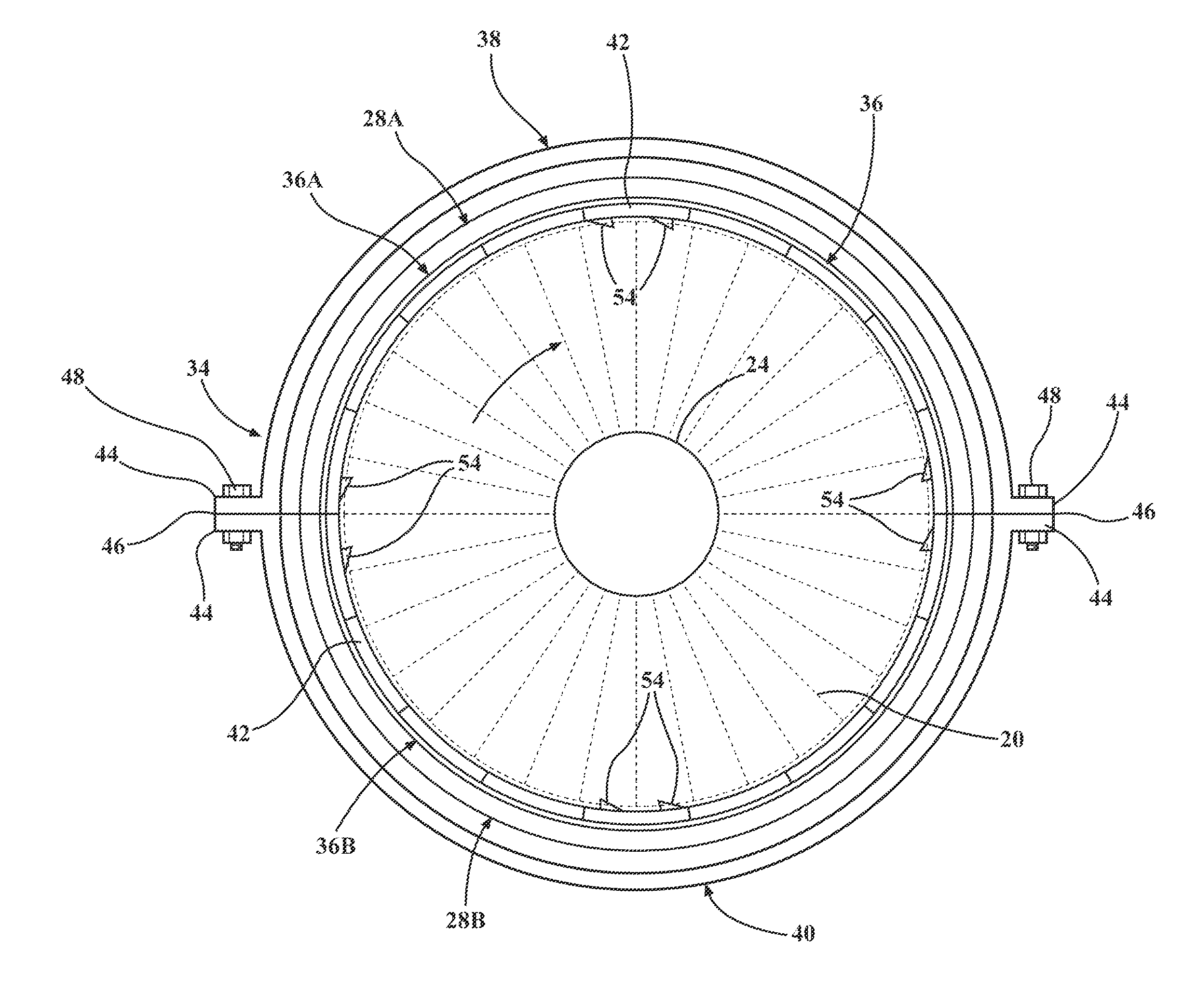
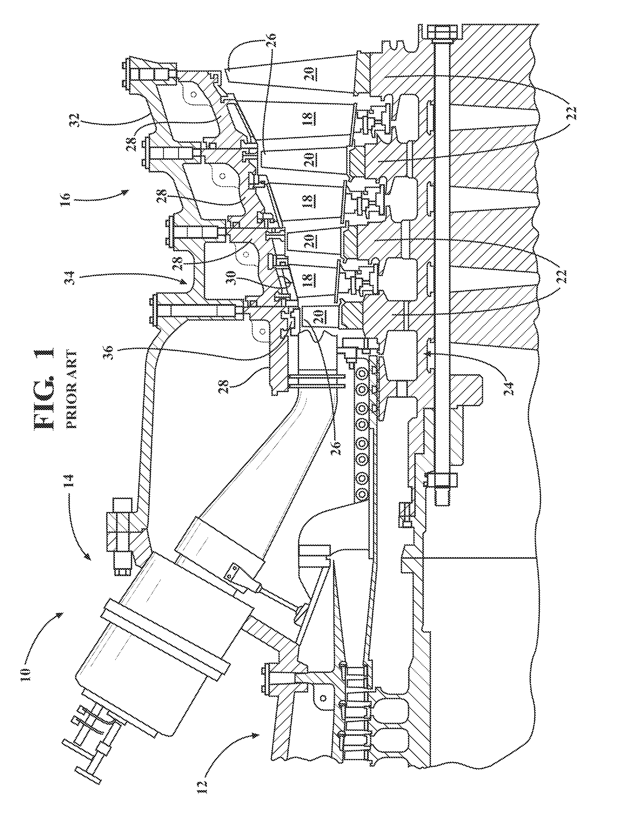
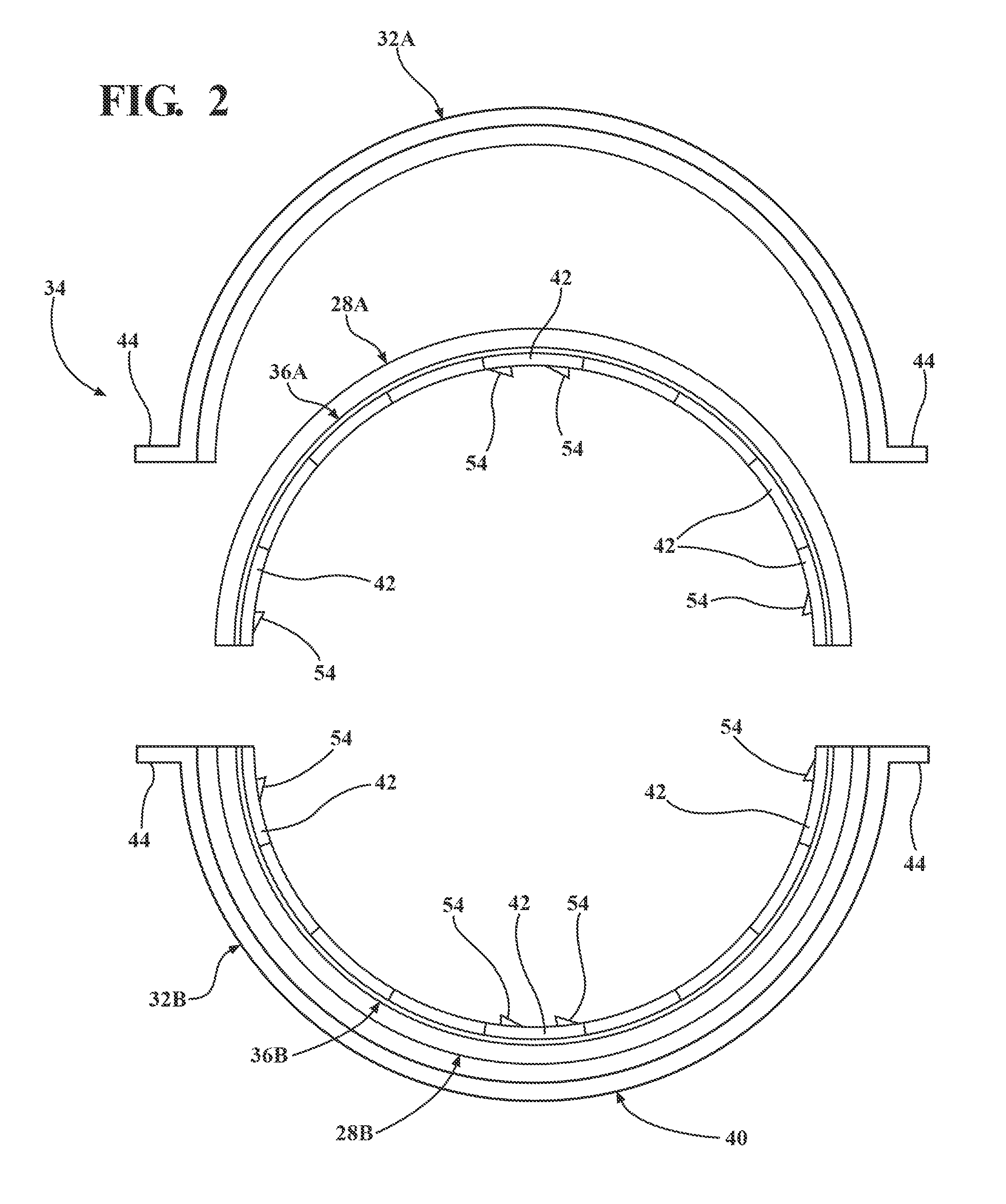
[0017]As described above with reference to the turbine engine 10 in FIG. 1, it is desirable to maintain a predetermined clearance between blade tips 26 and an inner surface 30 of an annular ring seal assembly 36. Further, in accordance with aspects of the present invention, it is desirable to maintain a predetermined clearance between the blade tips 26 and the seal assembly 36 when the engine 10 is in an assembled condition. That is, it is desirable to ensure that a designed clearance between the blade tips 26 and the seal assembly 36 is ...


PUM


Abstract

A measuring assembly for use in a gas turbine engine includes an indicia portion that extends radially inwardly from an inner surface of a ring seal structure to a location radially inwardly from tips of blades mounted on a rotor. The indicia portion of the measuring assembly comprises a section that is abraded by the blades during rotational movement of the rotor to provide a visual indication of a distance between the tips of the blades and the inner surface.

Description

FIELD OF THE INVENTION[0001]The present invention relates generally to a measuring assembly for use in a turbine engine, and more particularly, to a measuring assembly for determining a clearance between an inner surface of a seal structure in a turbine engine and tips of blades mounted to a rotor in the engine.BACKGROUND OF THE INVENTION[0002]Referring to FIG. 1, a turbine engine 10 is illustrated including a compressor section 12, a combustor section 14 and a turbine section 16. In the turbine section 16, there are alternating rows of stationary airfoils 18 (commonly referred to as vanes) and rotating airfoils 20 (commonly referred to as blades). Each row of blades 20 is formed by a plurality of airfoils 20 attached to discs 22 forming a rotor 24. The blades 20 extend radially outward from the discs 22 and terminate in a region known as the blade tip 26. Each row of vanes 18 is formed by attaching a plurality of vanes 18 to a vane carrier 28. The vanes 18 extend radially inwardly ...

Claims


Application Information

Patent Timeline
IPC IPC(8): F01D25/00G01B1/00G01M15/14
CPCF01D11/122F05D2240/11G01B5/14F01D17/02
Inventor CHEHAB, ABDULLATIF M.HINES, KEVIN L.PEPPERMAN, BARTON M.BOGDAN, MATTHEW D.
Owner SIEMENS ENERGY INC
Why Eureka
Try Eureka