Hybrid turbine tip clearance control system

a technology of control system and turbine, which is applied in the direction of leakage prevention, engine cooling apparatus, jet propulsion plants, etc., can solve the problems of nacelle loss, bleed air dumped, system limitation as to the minimum achievable tip clearance, etc., to reduce the temperature of the turbine support assembly, minimize the loss of parasitic secondary air system, and more flexibility

Inactive Publication Date: 2005-08-09
PRATT & WHITNEY CANADA CORP
View PDF35 Cites 42 Cited by
  • Summary
  • Abstract
  • Description
  • Claims
  • Application Information

AI Technical Summary

Benefits of technology

[0014]In one embodiment of the present invention, the second cooling air flow is introduced from a full pressure compressor air flow and cools the turbine shroud assembly continuously during the engine operation including a startup period thereof so that the turbine shroud segments will generally thermally respond to the full pressure compressor air temperature. Then, when the gas turbine engine has thoroughly stabilized and the pinch-point has been avoided, the first cooling air flow is used to cool the annular shroud housing. This first cooling air flow is introduced from the inter-stage compressor bleed air and can be regulated, for example by a control valve. Using inter-stage compressor bleed air for cooling the annular shroud housing provides more flexibility for tuning turbine tip clearance because the inter-stage compressor bleed air is from a lower temperature cooling source. The first cooling air flow, after being used to cool the annular shroud housing, is not wasted but is substantially re-used for cooling, for example the low pressure turbine stage one vanes. The benefit of re-using the first cooling air flow lies in that it minimizes parasitic secondary air system losses. It should also be noted that the double shroud support assembly configuration is adapted to accommodate the large thermal gradient from the gas path to the turbine support case, which contributes to achieving lower turbine support assembly temperatures, in contrast to prior art passive cooling systems. Therefore, overall engine performance is improved.

Problems solved by technology

It is desirable to maintain the gap between the blade tips and the shroud assembly as small as possible throughout the engine operation range because the combustion gas flowing therethrough bypasses the turbine blades and therefore provides no useful contribution.
When operating the engine during a transitional period, the thermal response rates of the casing and the rotor blades are difficult to match, thereby resulting in a pinch-point.
This pinch-point causes a system limitation as to the minimum achievable tip clearance without rubbing.
Typically, this inter-stage compressor bleed air is dumped into the nacelle and lost to the cycle after having cooled the turbine casing.
craft. The prior art offers complex solutions and solutions which do not maximize the efficiency of cooling air systems in the

Method used


Image

  • Hybrid turbine tip clearance control system
  • Hybrid turbine tip clearance control system
  • Hybrid turbine tip clearance control system

Examples


Embodiment Construction

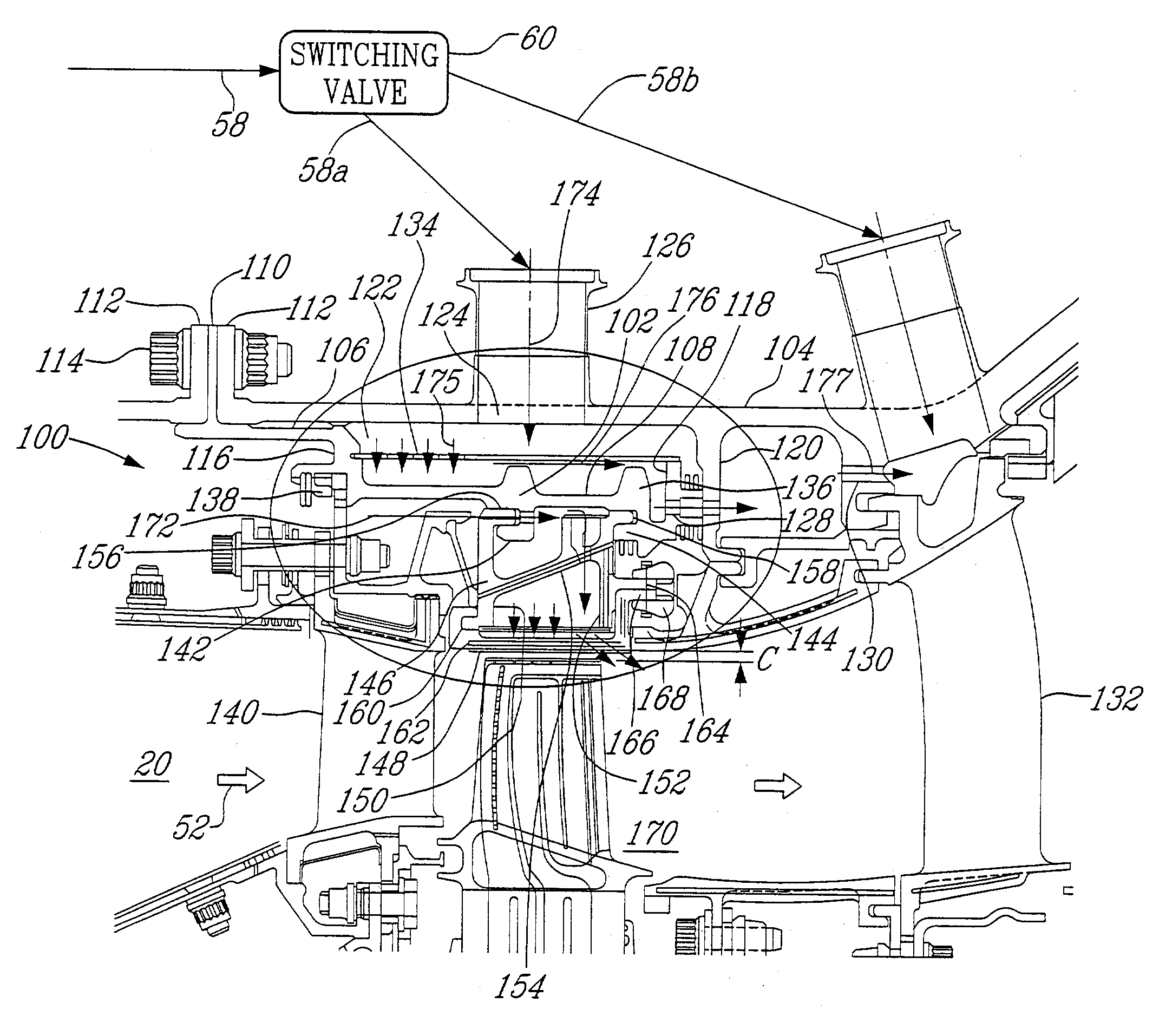
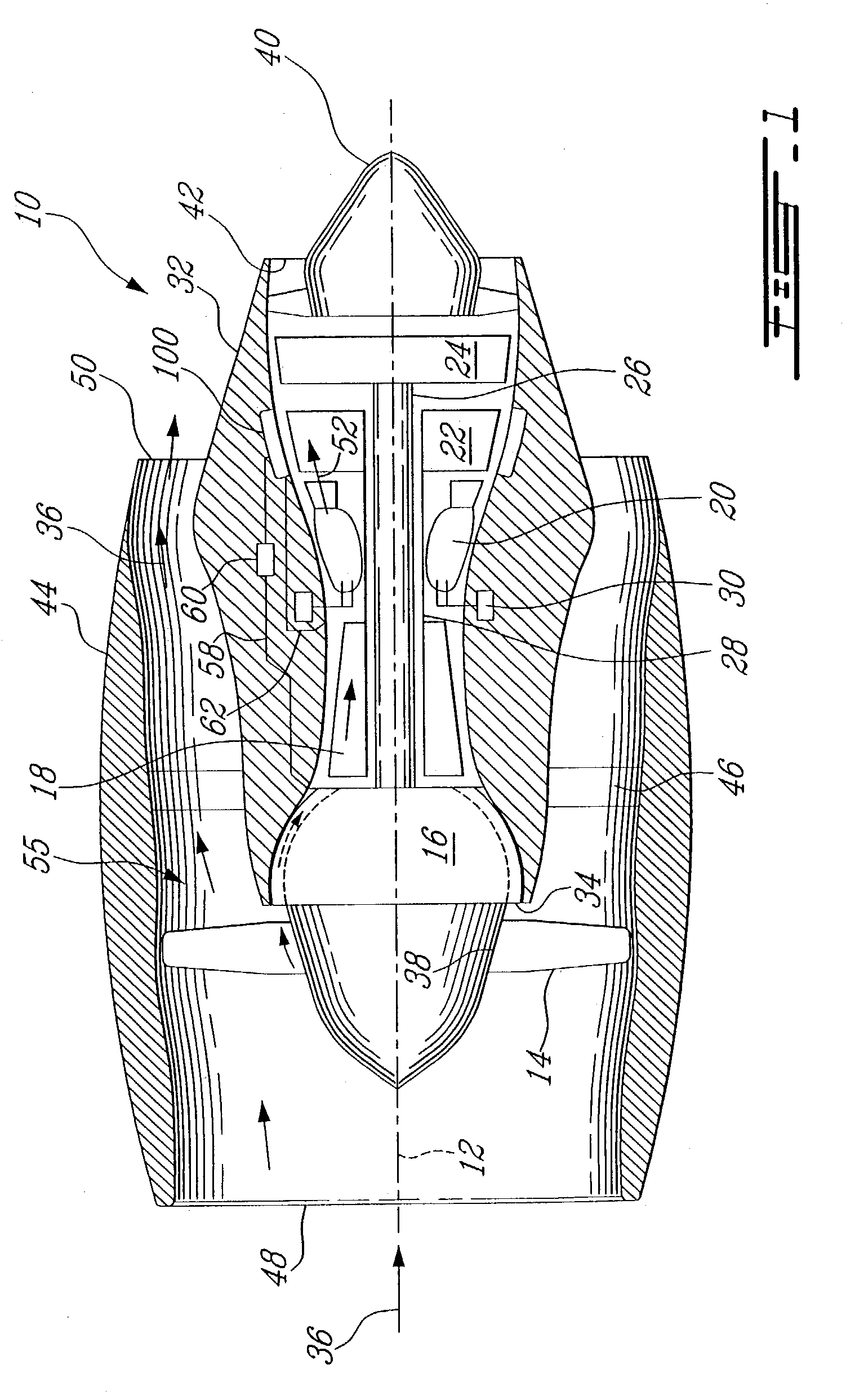
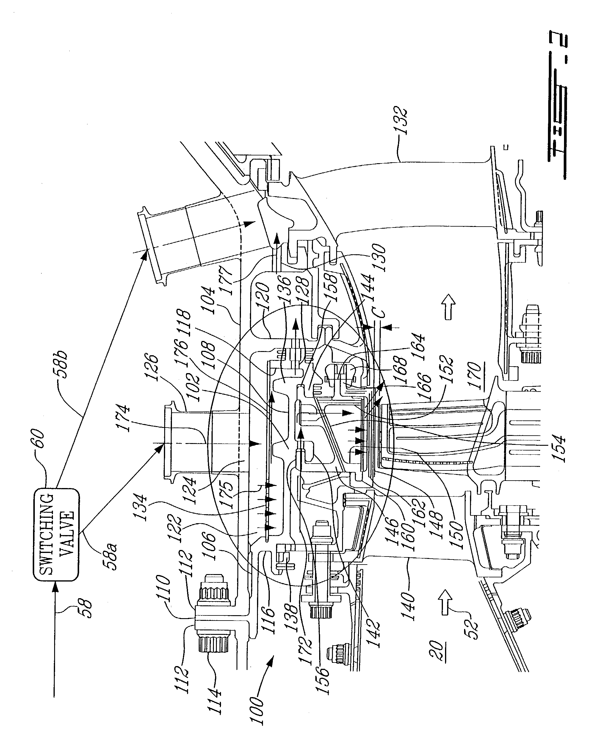
[0020]Referring to the drawings, particularly FIG. 1, a exemplary gas turbine engine 10 includes in serial flow communication about a longitudinal central axis 12, a fan having a plurality of circumferentially spaced apart fan or rotor blades 14, a conventional low pressure compressor 16, a conventional high pressure compressor 18, a conventional annular combustor 20, a high pressure turbine 22 which includes a turbine shroud support configuration 100 according to one embodiment of the present invention, and a conventional low pressure turbine 24. The low pressure turbine 24 is securely connected to both the low pressure compressor 16 and the fan blades 14 by a first rotor shaft 26, and the high pressure turbine 22 is securely connected to the high pressure compressor 18 by a second rotor shaft 28. Conventional fuel injecting means 30 are provided for selectively injecting fuel into the combustor 20, for powering the engine 10.

[0021]A conventional annular casing 32 surrounds the eng...


PUM


Abstract

A turbine shroud cooling system used in a gas turbine engine for controlling tip clearance between a turbine shroud assembly and turbine rotor blades comprises a cooling air passage for selectively directing a cooling air flow between components to be cooled and a turbine shroud support assembly for controlling the tip clearance and then later re-directing the cooling air flow to cool a downstream turbine component.

Description

FIELD OF THE INVENTION[0001]The present invention generally relates to gas turbine engines, and more particularly to clearance control between turbine rotor blade tips and a stator shroud assembly radially spaced apart therefrom.BACKGROUND OF THE INVENTION[0002]A gas turbine engine includes in serial flow communication, one or more compressors followed in turn by a combustor and high and low pressure turbines, disposed symmetrically about a longitudinal axis centerline within an annular outer casing.[0003]Each of the turbines includes one or more stages of rotor blades extending radially outwardly from respective rotor disks, with the blade tips being disposed closely adjacent to a turbine shroud assembly supported within the casing. It is desirable to maintain the gap between the blade tips and the shroud assembly as small as possible throughout the engine operation range because the combustion gas flowing therethrough bypasses the turbine blades and therefore provides no useful co...

Claims


Application Information

Patent Timeline
Patent Type & Authority Patents(United States)
IPC IPC(8): F01D11/10F01D11/24F01D11/08
CPCF01D11/10F01D11/24
Inventor WILSON, KEVINBOUCHARD, GUYMAKUSZEWSKI, JERZY
Owner PRATT & WHITNEY CANADA CORP
Why Eureka
Try Eureka