Turbine blade tip clearance control device

a control device and turbine blade technology, applied in the direction of machines/engines, stators, liquid fuel engines, etc., can solve the problems of inability to reduce the gap and the gap is minimal, and achieve the effect of reducing the gap size, reducing the leakage of air, and increasing the efficiency of the turbine engin

Inactive Publication Date: 2005-08-09
SIEMENS ENERGY INC
View PDF21 Cites 42 Cited by
  • Summary
  • Abstract
  • Description
  • Claims
  • Application Information

AI Technical Summary

Benefits of technology

[0005]This invention relates to a sealing system for reducing a gap between a tip of a shrouded turbine blade and a stationary shroud of a turbine engine. As a turbine engine reaches steady state operation, components of the sealing system reach their maximum expansion and reduce the size of the gap located between the blade tips and the engine shroud, thereby reducing the leakage of air past the turbine blades and increasing the efficiency of the turbine engine. In at least one embodiment, the sealing system includes a turbine blade assembly having at least one stage formed from a plurality of turbine blades.
[0007]The sealing system may also include one or more protrusions extending from the shroud of the turbine engine towards the tips of the turbine blades. The protrusions may extend circumferentially around the turbine blade assembly and may be positioned downstream of a seal land. In at least one embodiment, a protrusion may be positioned between two adjacent seal lands. The protrusions act as a dam to enhance the sealing ability of the sealing system.

Problems solved by technology

However, reducing the gap cannot be accomplished by simply positioning the components so that the gap is minimal under full load conditions because the configuration of the components forming the gap must account for emergency shutdown conditions in which the shroud, having less mass than the turbine blade and disc assembly, cools faster than the turbine blade assembly.
Collision of the turbine blades and the shroud often causes severe blade tip rubs and may result in damage.

Method used


Image

  • Turbine blade tip clearance control device
  • Turbine blade tip clearance control device
  • Turbine blade tip clearance control device

Examples


Embodiment Construction

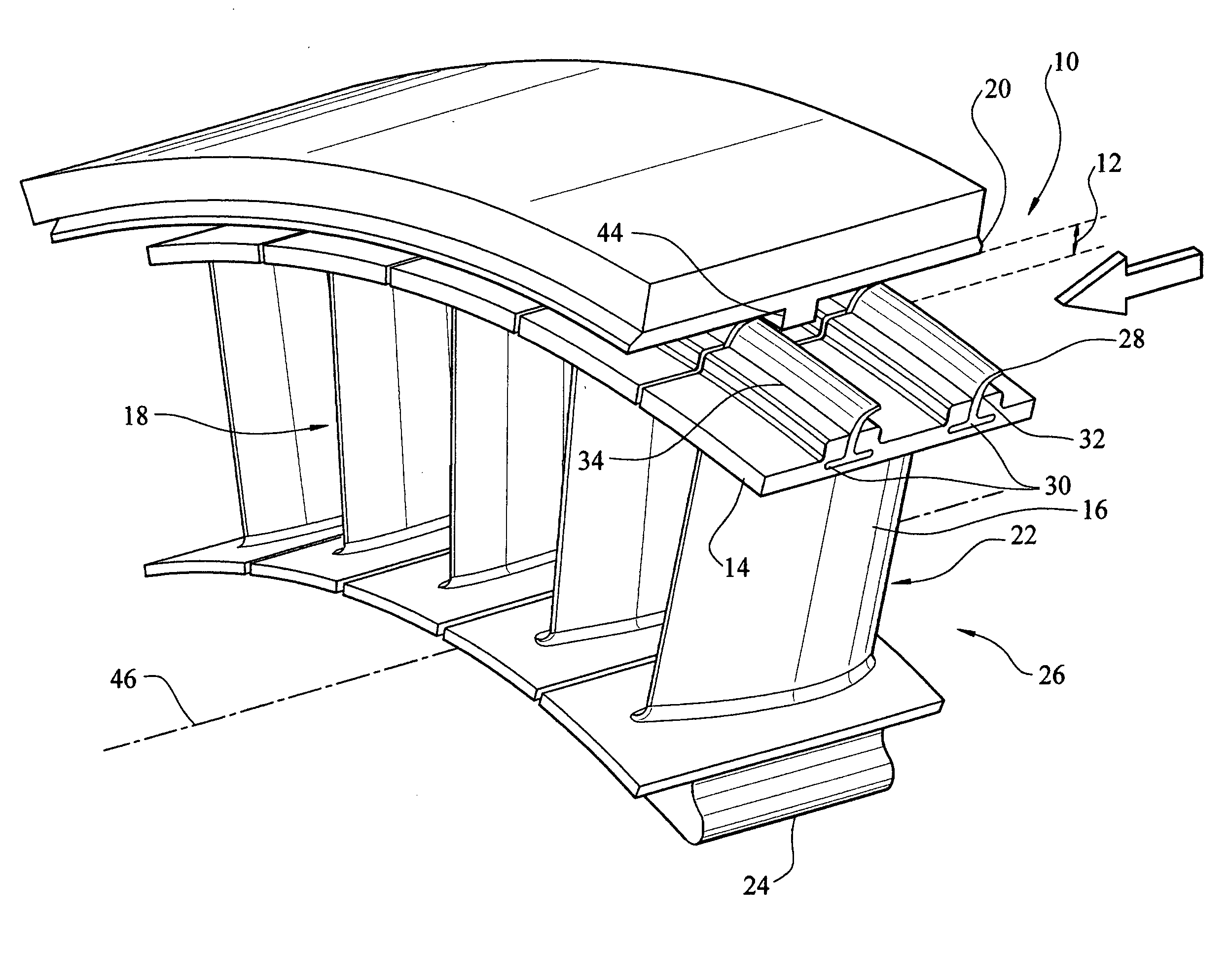
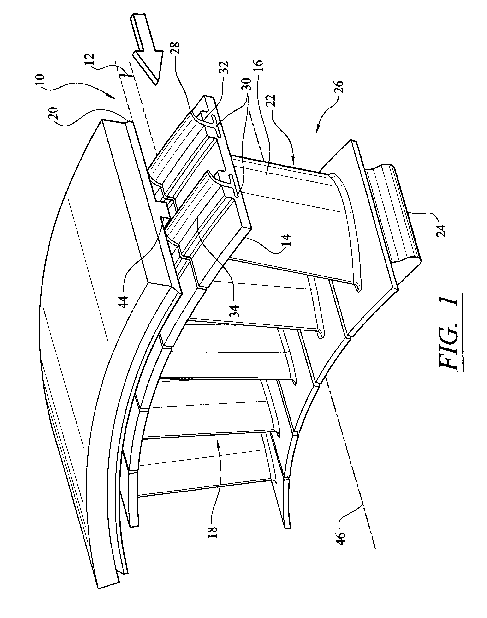
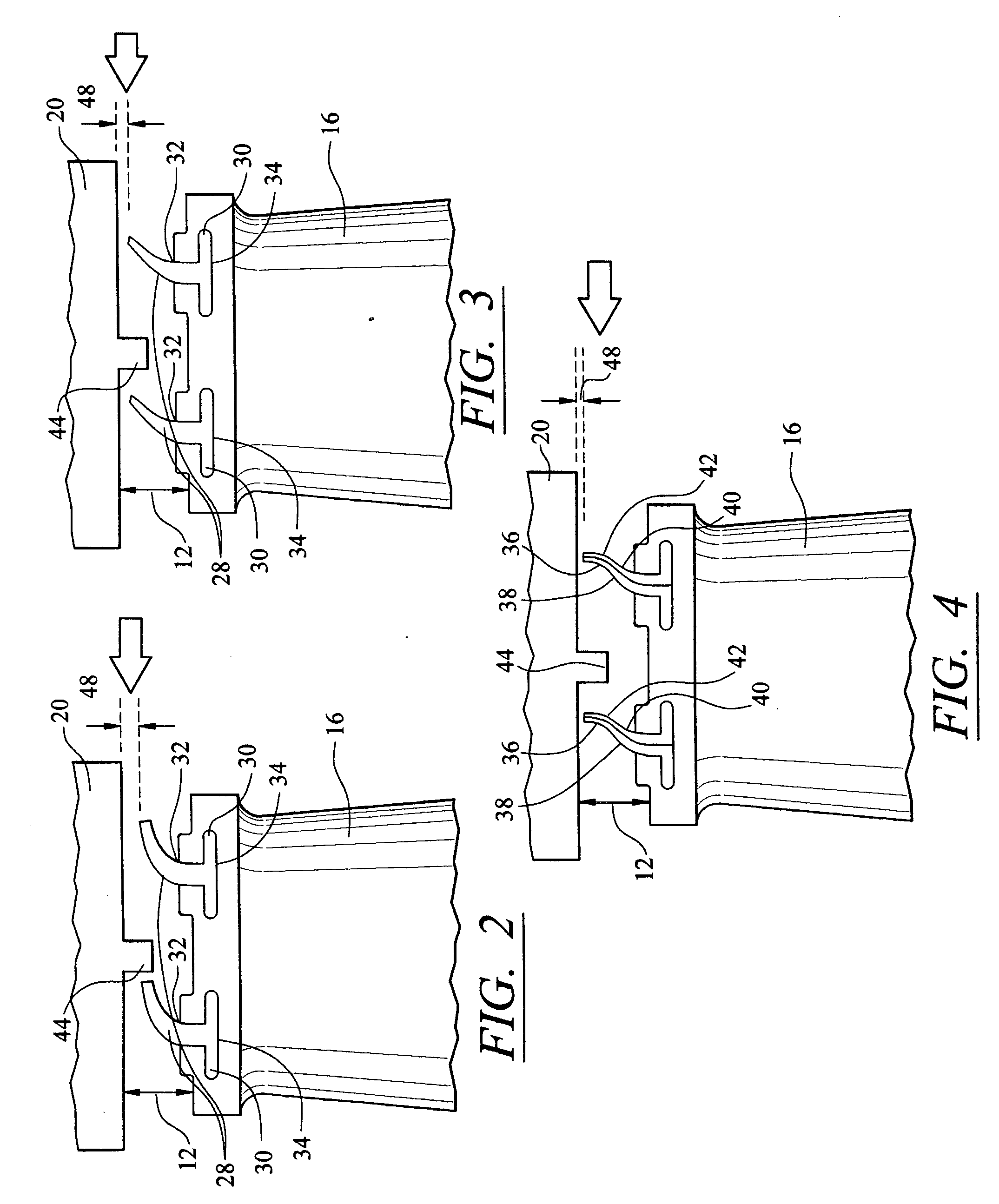
[0014]As shown in FIGS. 1–4, this invention is directed to a sealing system 10 usable in a turbine engine. In particular, the sealing system 10 is operable to reduce a gap 12 between one or more tip shrouds 14 of a turbine blade 16 in a turbine engine 18 and a surrounding stationary shroud 20 while the turbine engine 18 is operating. The sealing system 10 reduces the gap 12 to the gap 48. The gap 48 exists in the turbine engine 18 so that the tip shrouds 14 do not contact the stationary shroud 20 while the turbine engine 18 is at rest or is operating, or during assembly. In at least one embodiment, the turbine engine 18 includes a turbine blade assembly 22 formed at least in part from a plurality of turbine blades 16 coupled to a disc 24. The blades 16 may be coupled to the disc 24 at various points along the disc 24 and may be assembled into rows, which are commonly referred to as stages 26, having adequate spacing to accommodate stationary vanes (not shown) between adjacent stages...


PUM


Abstract

A sealing system for reducing a gap between a tip of a shrouded turbine blade and a stationary shroud of a turbine engine. The sealing system includes one or more seal lands extending from a shrouded turbine blade toward a stationary shroud of a turbine engine. During operation of the turbine engine, the seal lands straighten and extend towards the stationary shroud of the turbine engine, thereby reducing the leakage of air past the shrouded turbine blades and increasing the efficiency of the turbine engine. The sealing system may also include one or more protrusions extending from the stationary shroud towards the tips of the shrouded turbine blades.

Description

FIELD OF THE INVENTION[0001]This invention is directed generally to turbine engines, and more particularly to systems for sealing gaps between shrouded blade tips and stationary shrouds in turbine engines so as to improve turbine engine efficiency by reducing leakage.BACKGROUND[0002]Typically, gas turbine engines are formed from a combustor positioned upstream from a turbine blade assembly. The turbine blade assembly is formed from a plurality of turbine blade stages coupled to discs that are capable of rotating about a longitudinal axis. Each turbine blade stage is formed from a plurality of blades extending radially about the circumference of the disc. Each stage is spaced apart from each other a sufficient distance to allow turbine vanes to be positioned between each stage. The turbine vanes are typically coupled to the shroud and remain stationary during operation of the turbine engine.[0003]The tips of the turbine blades are located in close proximity to an inner surface of the...

Claims


Application Information

Patent Timeline
Patent Type & Authority Patents(United States)
IPC IPC(8): F01D11/00F01D11/02
CPCF01D5/225F01D11/02
Inventor DIAKUNCHAK, IHOR S.
Owner SIEMENS ENERGY INC
Why Eureka
Try Eureka