
Flow fixture for air cooling flow test on hollow blades

A hollow blade and flow test technology, which is used in aerodynamic tests, measuring devices, and testing of machine/structural components. The phenomenon of gas and flow restriction occurs, reduces the cycle of blade production and delivery, and ensures the effect of stability

Inactive Publication Date: 2015-08-19
CHINA HANGFA SOUTH IND CO LTD
View PDF6 Cites 18 Cited by
  • Summary
  • Abstract
  • Description
  • Claims
  • Application Information

AI Technical Summary

Problems solved by technology

[0005] The invention provides a flow fixture for the air-cooled air flow test of hollow blades to solve the problems of local flow limitation and air leakage in the existing old-fashioned flow test fixtures, poor sealing effect due to the inability to stably fix the blades, and poor sealing effect due to passing through bolts. Locking will easily lead to blade deformation or air leakage, which will easily lead to unstable test values. Repeated verification is required, resulting in technical problems that the blade has not been able to be submitted normally.

Method used


Image

  • Flow fixture for air cooling flow test on hollow blades
  • Flow fixture for air cooling flow test on hollow blades
  • Flow fixture for air cooling flow test on hollow blades

Examples


Embodiment Construction

[0024] The embodiments of the present invention will be described in detail below with reference to the accompanying drawings, but the present invention can be implemented in various ways defined and covered.

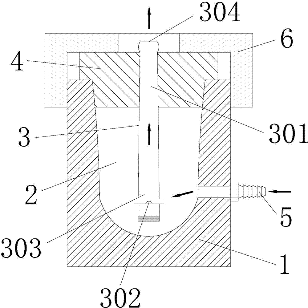
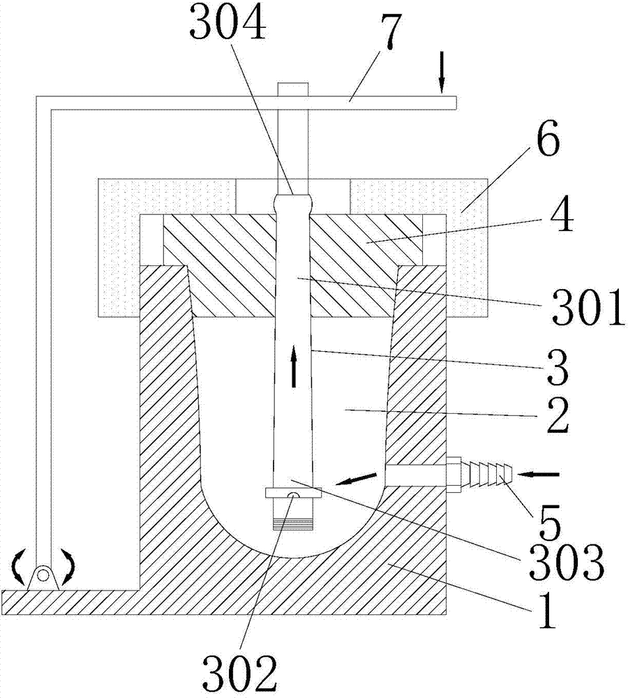
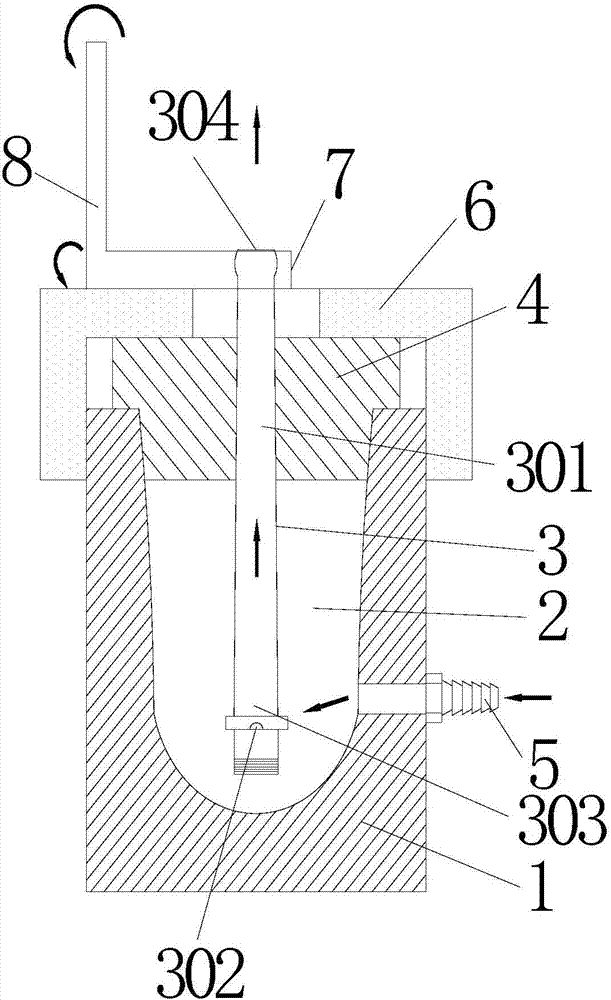
[0025] figure 1 It is one of the structural schematic diagrams of the flow fixture used for the air-cooled air flow test of the hollow blade according to the preferred embodiment of the present invention; figure 2 It is the second structural schematic diagram of the flow fixture used for the air-cooled air flow test of the hollow blade according to the preferred embodiment of the present invention; image 3 It is the third schematic diagram of the structure of the flow clamp used for the air-cooled air flow test of the hollow blade according to the preferred embodiment of the present invention.

[0026] Such as figure 1 As shown, the flow fixture used for the air-cooled air flow test of the hollow blade in this embodiment includes a fixture body 1 with an opening on ...


PUM


Abstract

The present invention discloses a flow fixture for the air cooling flow test on hollow blades, which comprises a fixture body with an opening on one side thereof. The fixture body is provided with a fixture inner cavity used for the levitation of a hollow blade and communicated with the outside through the opening, a seal gasket covered onto the outer surface of he hollow blade and closed inside the opening of the fixture inner cavity, and a fixture air inlet for being connected with a flow tester and feeding the cooling air into the fixture inner cavity. The tenon air inlet of the hollow blade and the lower margin plate of the hollow blade are positioned in the fixture inner cavity. The shrouded air outlet of the hollow blade is positioned inside the fixture inner cavity to be communicated with the outside, so that a flow channel for the cooling air is formed, wherein the cooling air flows into the flow channel through the fixture air inlet and flows out of the flow channel through the shrouded air outlet. In this way, the stability of measured results is ensured and the floating error of measured results on a single part during multiple tests is almost zero. Therefore, whether the blade is qualified or not can be quickly tested. The production and delivery period of the blade is shortened.

Description

technical field [0001] The invention relates to the technical field of turbofan engine turbine working blade detection, in particular to a flow fixture used for the air-cooled air flow test of a hollow blade. Background technique [0002] The working environment of a certain type of high-pressure turbine working blade is harsh, and it should have good thermal strength, fatigue resistance and creep performance. The blade adopts a hollow structure, that is, the cold air enters through the air inlet of the tenon teeth, and is discharged from the outlet of the blade tip through the inner cavity of the blade, so as to achieve the function of ventilation and cooling, and protect the blade. [0003] In order to ensure the cooling effect of the blades, before the high-pressure turbine blades are processed and put into storage, a single piece of air-cooled air flow test must be carried out according to the process data, that is, under the pressure of 0.08MPa, the measured flow rate i...

Claims


Application Information

Patent Timeline
Patent Type & Authority Applications(China)
IPC IPC(8): G01M9/00
Inventor 黄文俊张雅琼张菊绒杨锦詹妮
Owner CHINA HANGFA SOUTH IND CO LTD
Learn More