Blades for a gas turbine engine with integrated sealing plate and method

a gas turbine engine and sealing plate technology, applied in the direction of propellers, propulsive elements, water-acting propulsive elements, etc., can solve the problems of substantial gaps between the blades, significantly reduce the efficiency of gas turbine engines, and not adequately seal this area, so as to reduce the leakage of cooling air

Active Publication Date: 2009-02-03
PRATT & WHITNEY CANADA CORP
View PDF22 Cites 20 Cited by
  • Summary
  • Abstract
  • Description
  • Claims
  • Application Information

AI Technical Summary

Benefits of technology

[0006]It is therefore an aim of the present invention to provide an improved rotor blade for reducing cooling air leakage through gaps between adjacent blades.

Problems solved by technology

In some engine designs, the gaps between the blades can be substantial and conventional cover plates mounted on the rotor disc generally do not adequately seal this area.
This transverse cooling air leakage flow impedes and disturbs the gas path flow and can significantly reduce the gas turbine engine efficiency.
However, such a ring can be subject to unwanted movement or be misplaced during assembly or maintenance, thereby reducing its efficiency.
Moreover, damage at one point of the ring necessitates the replacement of the entire ring.

Method used


Image

  • Blades for a gas turbine engine with integrated sealing plate and method
  • Blades for a gas turbine engine with integrated sealing plate and method
  • Blades for a gas turbine engine with integrated sealing plate and method

Examples


Embodiment Construction

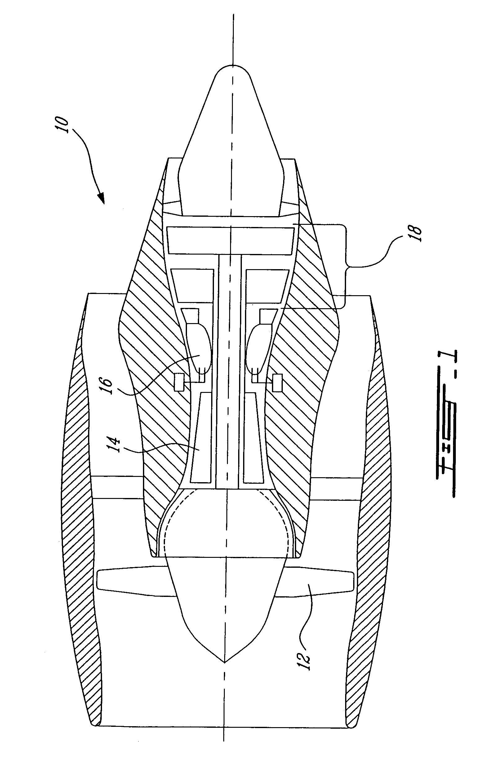
[0016]FIG. 1 illustrates a gas turbine engine 10 of a type preferably provided for use in subsonic flight, generally comprising in serial flow communication a fan 12 through which ambient air is propelled, a multistage compressor 14 for pressurizing the air, a combustor 16 in which the compressed air is mixed with fuel and ignited for generating an annular stream of hot combustion gases, and a turbine section 18 for extracting energy from the combustion gases.

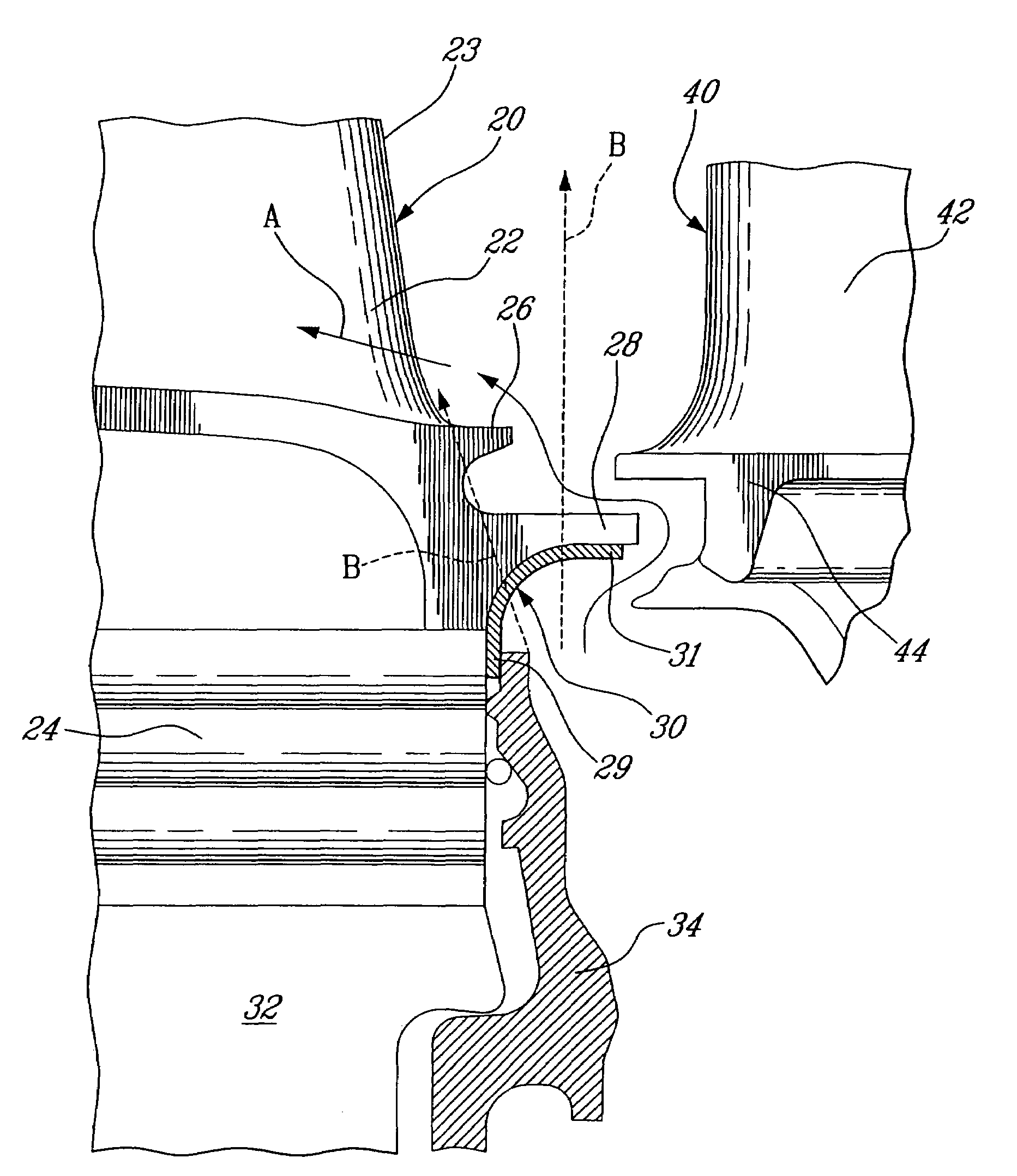
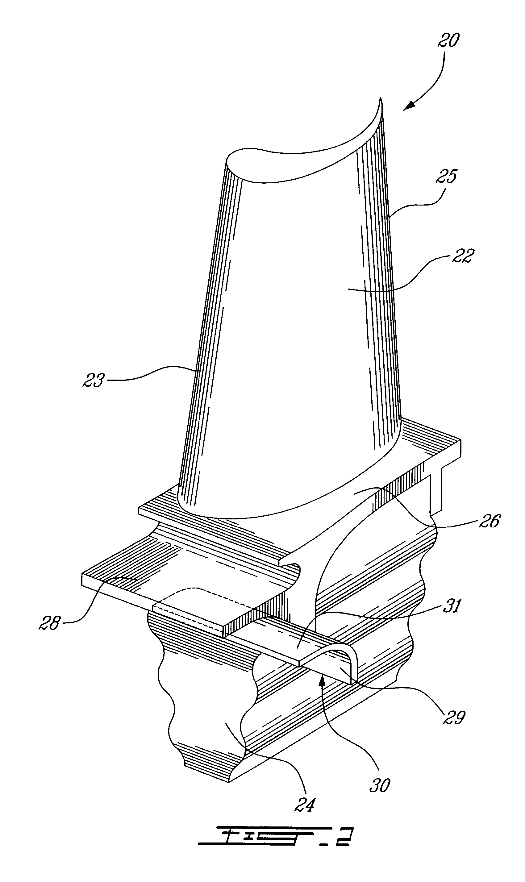
[0017]Referring to FIGS. 2-3, a rotor blade 20 for use in the turbine section 18 is shown. The rotor blade 20 includes an airfoil portion 22, a platform 26 and a blade root 24. It is to be understood that the rotor blade 20 can also be used in a variety of other rotors such as, for example, rotors of the compressor 14.

[0018]The blade root 24 is shaped to correspond with one of a plurality of circumferentially distributed slots in a rotor disc 32. The platform 26 has an underside connected to the blade root 24, and a top side co...


PUM


Abstract

A blade for a rotor assembly including a root portion, a platform with an overhang, an airfoil portion and a sealing plate. The sealing plate protrudes from the blade along a circumferential direction.

Description

TECHNICAL FIELD[0001]The present invention relates generally to gas turbine engines and, more particularly, to improved rotor blades of such engines and a method related thereto.BACKGROUND OF THE ART[0002]A conventional gas turbine engine is generally provided with one or more rotor assemblies with a disc and a circumferential array of blades. The rotor blades are disposed in corresponding retention slots of the disc with a radially extending gap between adjacent blades to accommodate thermal expansion. These rotor assemblies are used in the turbine section, the compressor section, or both. The blades are often provided with internal cooling channels, especially when used in the turbine section.[0003]In some engine designs, the gaps between the blades can be substantial and conventional cover plates mounted on the rotor disc generally do not adequately seal this area. Cooling air can leak through these radial gaps and the blades, which produce an impeller effect due to their extreme...

Claims


Application Information

Patent Timeline
Patent Type & Authority Patents(United States)
IPC IPC(8): F01D11/00
CPCF01D11/006F01D5/3015F01D11/001
Inventor BOUCHARD, GUYTRUMPER, RONALD
Owner PRATT & WHITNEY CANADA CORP
Why Eureka
Try Eureka