Differential motion airtight feeding electric furnace smelting device and feeding method thereof

A technology of electric furnace smelting and feeding device, which is applied in the field of metallurgy, can solve the problems of dioxin emissions that cannot meet environmental protection indicators, the laying thickness cannot be too large, and the transmission power can be reduced, so as to reduce equipment maintenance and auxiliary energy consumption. Probability of generation of harmful components, effect of reducing dust content and discharge temperature

Active Publication Date: 2011-09-14
CISDI ENG CO LTD
View PDF11 Cites 19 Cited by
  • Summary
  • Abstract
  • Description
  • Claims
  • Application Information

AI Technical Summary

Problems solved by technology

[0021] 1) The amount of dust in the settling chamber of conventional electric furnace flue gas dust removal is relatively large, and the dust contains high recyclable components;
[0022] 2) Conventional electric furnace production needs to open the cover and add scrap steel, the heat loss and power consumption of the electric furnace are high, and the production environment is harsh;
[0023] 3) Conventional electric furnace production requires frequent mechanical operations, and the maintenance of equipment is relatively large;
[0024] 4) The CONSTEEL scrap steel conveying device system is too long, adopts horizontal conveying, the equipment vibrates greatly, it is inconvenient to start and stop, the conveying efficiency is low, and the floor area is large
[0025] 5) The dynamic sealing of CONSTEEL steel scrap from the receiving chute to the heating section has a large air mixing, which will increase the fan capacity (see the listed documents);
[0026] 6) CONSTEEL has high requirements for steel scrap (light and thin material), and poor adaptability to raw material transportation;
[0027] 7) In the conveying scheme proposed by CISDI, the core adopts the chute conveying, and the chute conveying uses the gravity of the object to convey, which can greatly reduce the conveying power (power induction only controls the feeding speed), and can speed up the feeding speed, but brings The problem is that the tail of the equipment is gradually raised, and the high-strength feeding of scrap steel required by the continuous production of electric furnaces has brought a huge challenge to this scheme. CN201010170509.2 first proposed the feeding of long-shaped feeding troughs for the shimmy chute, but the long-shaped The stacking height and flatness of the feeding trough cannot be accurately controlled, which brings new challenges to the cold air seal at the inlet. At the same time, due to the adhesion between the scrap steel, the scrap steel cannot be conveyed from the receiving conveying trough to the hot conveying trough. Smooth, prone to problems such as material jamming, which limits the laying thickness of scrap steel in the receiving trough to not be too large, resulting in the problem of low feeding efficiency. If this problem is not solved, the technology cannot be implemented in projects. Other CISDI patents of the same family The problems faced by are similar;
[0028] 8) Since the flue gas directly preheats the scrap steel, the emission of dioxin cannot meet the environmental protection index
[0029] Therefore, it is necessary to improve the existing electric furnace smelting device, and propose a new feeding method and smelting method to solve the problem of scrap steel sticking in the process of conveying, improve the feeding efficiency, and also reduce the energy in the scrap steel smelting process. Reduce energy consumption and heat loss, weaken the function of flue gas to directly preheat scrap steel, and realize the comprehensive optimization of high efficiency, energy saving, environmental protection and investment in the production process

Method used


Image

  • Differential motion airtight feeding electric furnace smelting device and feeding method thereof
  • Differential motion airtight feeding electric furnace smelting device and feeding method thereof
  • Differential motion airtight feeding electric furnace smelting device and feeding method thereof

Examples


Embodiment Construction

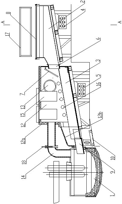
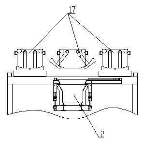
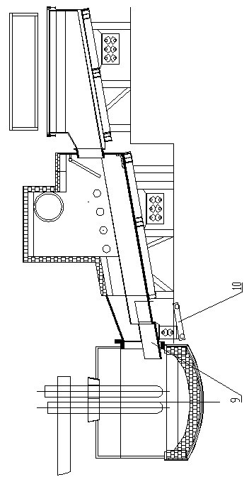
[0061] The present invention will be described in detail below in conjunction with the accompanying drawings, as shown in the figure: the electric furnace smelting device for differential airtight feeding in this embodiment includes an electric furnace 1 and a charging device, and the charging device includes a cold receiving conveying tank 2 and a hot conveying trough 3, an independently controlled vibration excitation device I4 is provided under the cold receiving material delivery tank 2, an independently controlled vibration excitation device II5 is provided under the hot delivery tank 3, and an extension into the conveying throat 6 in the heat conveying trough 3, the distance between the conveying throat 6 and the bottom of the heat conveying trough 3 is equal to or greater than the depth of the heat conveying trough 3, the distance between the cold receiving conveying trough and the hot conveying trough space The height difference makes the vibration excitation device Ⅰ a...


PUM


Abstract

The invention discloses a differential motion airtight feeding electric furnace smelting device and a feeding method thereof. The device comprises an electric furnace and a charging device, wherein the charging device comprises a cold receiving conveying trough and a heat conveying trough; the lower sides of the cold receiving conveying trough and the heat conveying trough are provided with an independently-controlled excitation device respectively; the outlet of the cold receiving conveying trough is provided with a conveying throat opening which is extended into the heat conveying trough; and the distance between the conveying throat opening and the bottom of the heat conveying trough is greater than or equal to the depth of the heat conveying trough. By the feeding method, shock excitation at different frequencies is applied to the two conveying troughs to realize the differential motion conveying of raw materials, so that a thicker material layer can be laid on the cold receiving conveying trough, and the material loading speed is increased; simultaneously, a shorter cold receiving conveying trough and a shorter material-conveying bottom elongated slot can be designed, so that the device and the method make project implementation convenient. In addition, due to the adoption of the throat opening and a sealed door structure, the possibility of material blocking and the air leakage rate are greatly reduced, and the device has low heat loss and a good dedusting effect, and is high-efficient, energy-saving and environment-friendly during smelting.

Description

technical field [0001] The invention belongs to the technical field of metallurgy, and in particular relates to an electric furnace smelting device and a differential airtight conveying method for raw materials in the smelting process. Background technique [0002] Electric furnace smelting is an important steelmaking method. It melts scrap metal by electric arc. For example, a large amount of electric energy will be consumed in the process of electric furnace steelmaking. At present, the cost of electric energy consumption for all scrap steel smelting accounts for 8-9% of the production cost. Among the consumed electric energy, in addition to the electric energy consumed by melting metal, the heat dissipation of the furnace body and the heat taken away by the flue gas during the operation of the electric furnace body reach 100kwh / t and 140kwh / t respectively, which together account for about 100kwh / t and 140kwh / t of electric furnace smelting power consumption. In addition, i...

Claims


Application Information

Patent Timeline
Patent Type & Authority Applications(China)
IPC IPC(8): C21C5/52F27D3/00
CPCY02P10/20
Inventor 黄其明徐杰高瞻刘向东
Owner CISDI ENG CO LTD
Why Eureka
Try Eureka