Power supply equipment utilizing interchangeable tips to provide power and a power indication signal to an electronic device

a technology of power supply equipment and power indication signal, which is applied in the direction of coupling device connection, safety/protection circuit, instruments, etc., can solve problems such as problems such as problems such as problems such as airplane crash or substantial damage, and battery overheating or even catching fir

Active Publication Date: 2012-08-23
COMARCO WIRELESS TECH
View PDF2 Cites 14 Cited by
  • Summary
  • Abstract
  • Description
  • Claims
  • Application Information

AI Technical Summary

Problems solved by technology

However, if the charging circuitry in the battery malfunctions, the battery can overheat or even catch on fire when recharging from an EMPOWER DC source.
If the battery were to catch on fire while an airplane in which the emPlower outlet is located is flying, the fire would have the potential to cause the airplane to crash or cause substantial damage.
However, problems arise when the user forgets to change the connector 115 for use with the automobile when the user is in an airplane.
Accordingly, if the user has the wrong connector 115 attached when using with the EMPOWER system, a battery of an electronic device 120 such as a notebook computer can charge the battery even when used with the EMPOWER system, and if the charging circuitry of the battery malfunctions, overheating or even a fire can occur, resulting in damage to the notebook computer.
Also, if the connector 115 is damaged or flawed, then it may not provide the correct Vdata signal to the notebook computer, allowing the notebook computer to recharge the batteries in an airplane when they shouldn't be allowed to do so.
Accordingly, current DC / DC power adapter systems are deficient because they are incapable of automatically and intelligently informing an electronic device 120 coupled thereto of the DC power source (i.e., the EMPOWER system or an automobile cigarette lighter outlet).

Method used


Image

  • Power supply equipment utilizing interchangeable tips to provide power and a power indication signal to an electronic device
  • Power supply equipment utilizing interchangeable tips to provide power and a power indication signal to an electronic device
  • Power supply equipment utilizing interchangeable tips to provide power and a power indication signal to an electronic device

Examples


Embodiment Construction

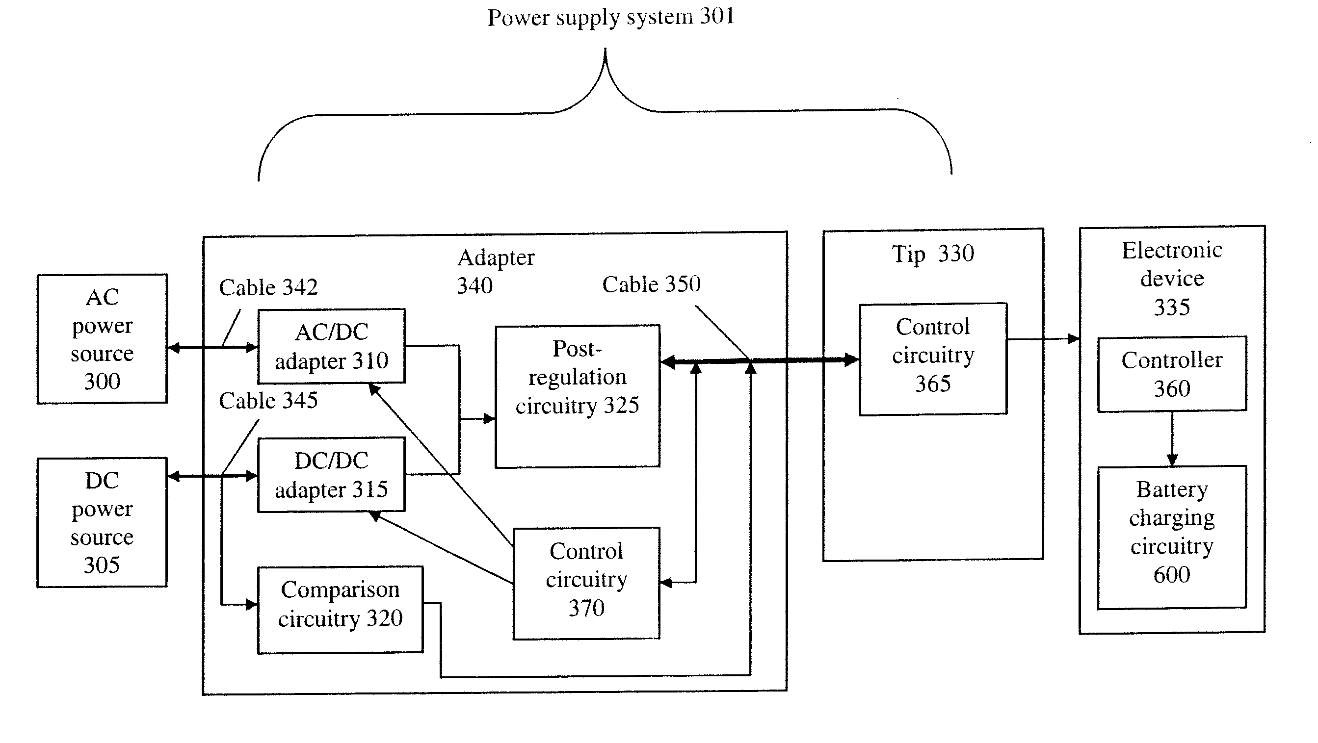
[0024]An embodiment of the present invention is directed to a power supply system to determine a DC power source (e.g., an automobile cigarette lighter outlet or an EMPOWER airplane outlet) coupled thereto and send a signal indicative of the power source to an electronic device coupled thereto. The electronic device may be a notebook computer or other portable consumer electronic device, for example. Based on the signal sent to the electronic device, the electronic device may control the amount of power drawn to prevent overheating. For example, when a notebook computer is hooked up and the power source is the EMPOWER system, the electronic device may disable charging of the internal batteries of the notebook computer, in order to prevent damage or overheating of the batteries due to malfunction or failure. The DC power source may be determined by voltage comparison circuitry, such as a comparator, or by a voltage comparison device including a processor.

[0025]FIG. 3 illustrates a po...


PUM


Abstract

Power supply equipment includes an adapter which converts power from a power source to DC power for powering an electronic device. The power supply equipment includes circuitry which produces a power indication signal for use by the electronic device to control power drawn by the electronic device. A cable, which is electrically coupled to the adapter, has a connector at its distal end. The power supply equipment further includes a tip which has an input connector and an output connector. The input connector of the tip is detachable mateable to the connector on the distal end of the cable. The output connector of the tip is detachably mateable to the electronic device. The tip output connector has a shape and size dependent on the shape and size of a power input opening of the electronic device. The tip provides the power indication signal, as well as the DC power, to the device.

Description

RELATED APPLICATIONS[0001]This application is a continuation-in-part of application Ser. No. 13 / 209,636, filed on Aug. 15, 2011, which is a continuation of application Ser. No. 12 / 840,952, filed on Jul. 21, 2010, now U.S. Pat. No. 7,999,412 issued on Aug. 16, 2011, which is a continuation of application Ser. No. 11 / 604,950, filed on Nov. 28, 2006, now U.S. Pat. No. 7,868,486 issued on Jan. 11, 2011, which is a continuation-in-part of application Ser. No. 10 / 758,933, filed on Jan. 15, 2004, now U.S. Pat. No. 7,453,171 issued on Nov. 18, 2008.BACKGROUND OF THE INVENTION[0002]1. Technical Field[0003]This invention relates to DC power adapters for powering electronic devices.[0004]2. Description of the Related Arts[0005]There are power systems in the art which allow a user to hook up a DC / DC adapter to an automobile outlet, to supply regulated DC power to power an electronic device, such as a notebook computer. Automobile outlets typically provide a DC voltage in a range between 11.0 an...

Claims


Application Information

Patent Timeline
Patent Type & Authority Applications(United States)
IPC IPC(8): G05F1/00
CPCH01R29/00H02J7/0055H02J7/0029H02J1/00G05F1/00H02J2207/40H02J7/00309H02J7/00
Inventor LANNI, THOMAS W.
Owner COMARCO WIRELESS TECH
Why Eureka
Try Eureka