Maximizing illumination fiber in an endoscope

a technology of illumination fiber and endoscope, which is applied in the field of endoscopes, can solve problems such as image quality suffers, and achieve the effect of maximizing the illumination of an obj

Active Publication Date: 2012-08-23
INTUITIVE SURGICAL OPERATIONS INC
View PDF8 Cites 3 Cited by
  • Summary
  • Abstract
  • Description
  • Claims
  • Application Information

AI Technical Summary

Benefits of technology

[0008]Therefore, it is an object of this invention to provide a multiple channel endoscope that maximizes illumination of an object at the distal end thereof.

Problems solved by technology

Consequently, in many instances, particularly as stereoscopic endoscopes are made with smaller outside diameters, image quality suffers.

Method used


Image

  • Maximizing illumination fiber in an endoscope
  • Maximizing illumination fiber in an endoscope
  • Maximizing illumination fiber in an endoscope

Examples


Embodiment Construction

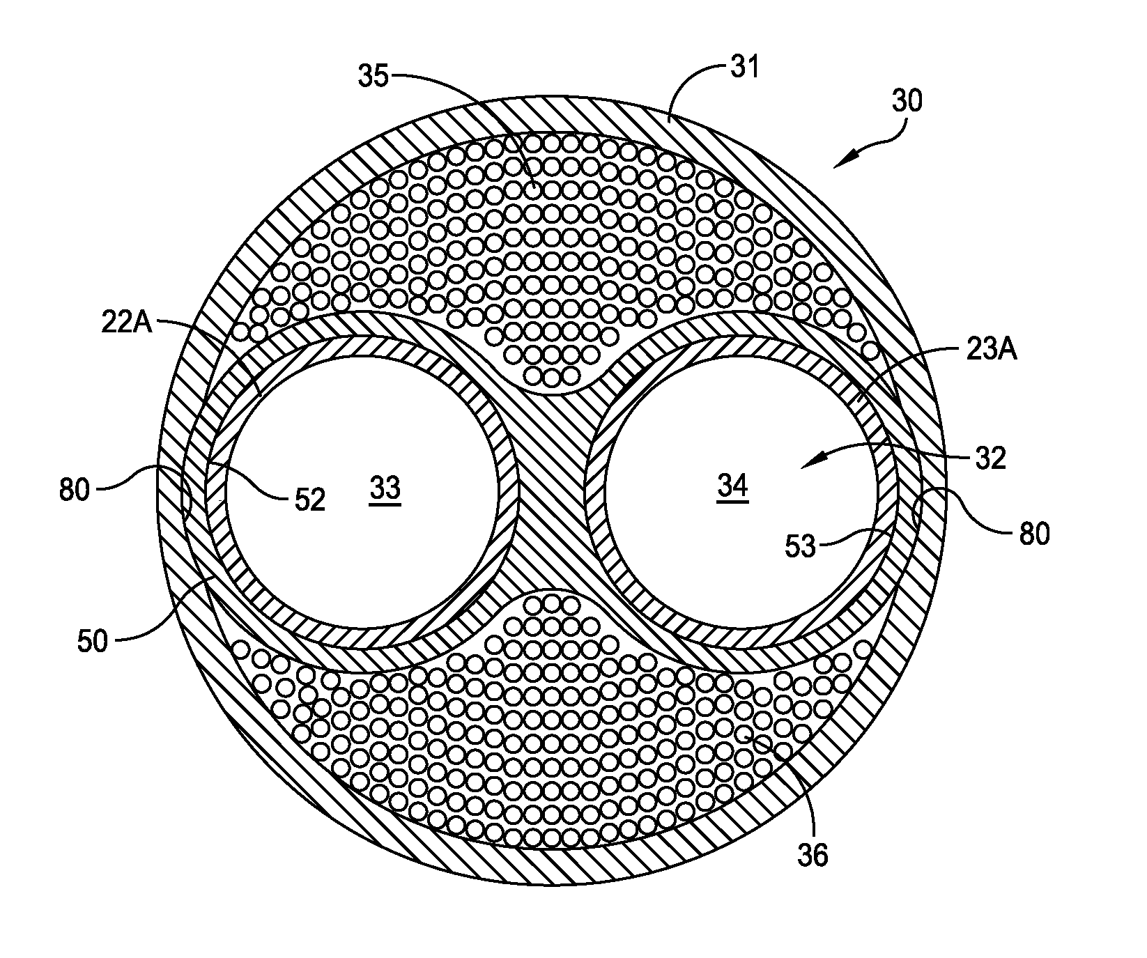
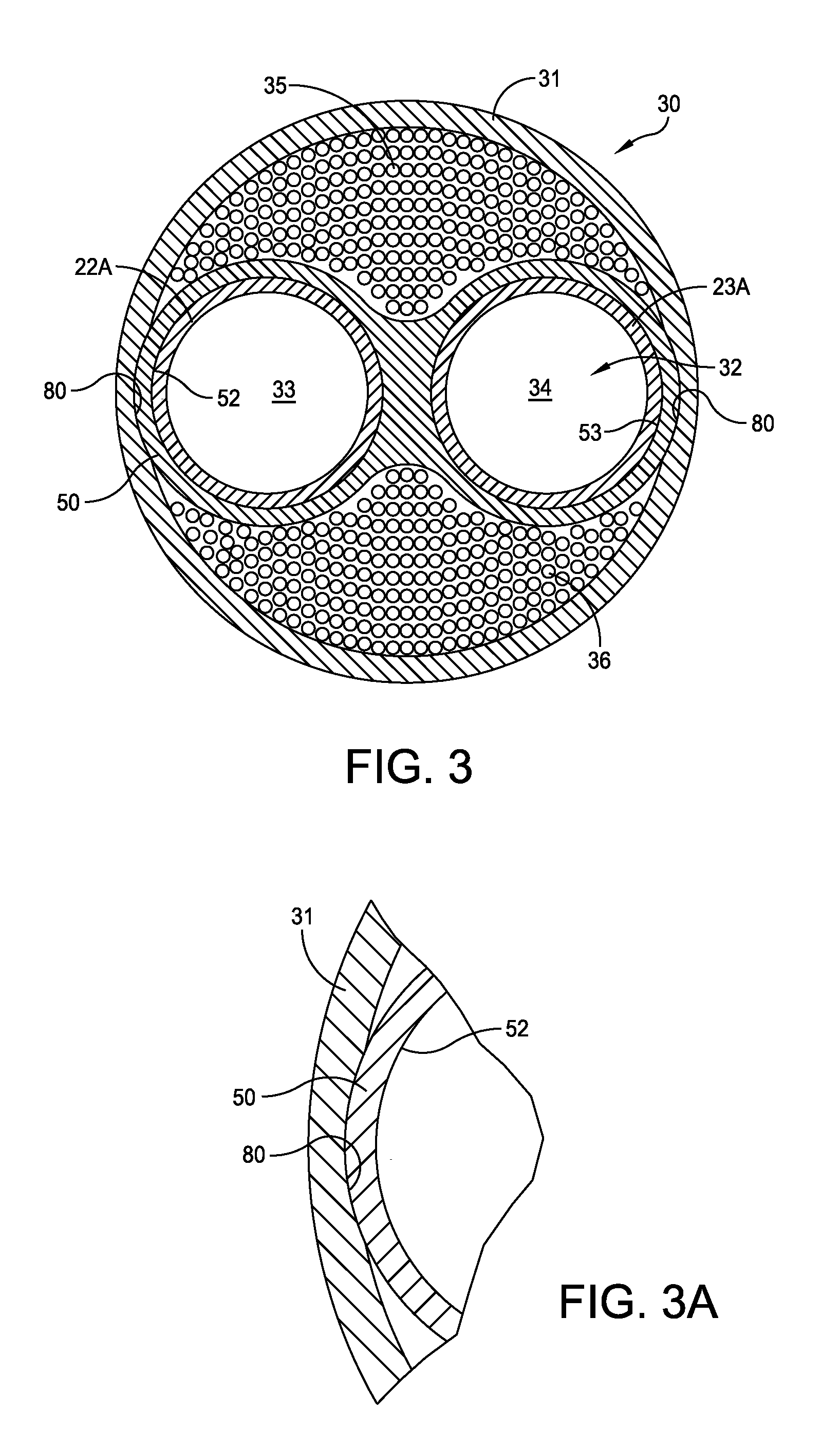
[0023]FIG. 3 depicts a cross-section adjacent the distal end of a stereoscopic endoscope 30 that incorporates this invention. The endoscope 30 includes an outer tube 31 and, in accordance with this invention, an insert having the characteristics of one such insert in accordance with this invention. The insert 32 defines parallel passages 33 and 34. Each of the passages 33 and 34 has a diameter adapted to receive and support ends of the inner tubes 22A and 23A that carry image forming subassemblies (i.e., the optical train subassemblies) to provide two optical channels in a close fitting relationship. As described later, a similar insert is located at the proximal end of the endoscope. Optical fiber bundles 35 and 36 substantially fill non-circular voids between the inner surface of the outer tube 31 and the opposite sides of the distal insert 32. As a consequence, a stereoscopic endoscope constructed in accordance with this invention provides a maximum illumination transfer from the...


PUM


Abstract

A stereoscopic endoscope includes a proximal main body, an outer tube extended to a distal end of the endoscope and a pair of optical train subassemblies. Distal and proximal inserts in the distal and proximal ends of the outer tube, respectively, support the optical train subassemblies. First and second optical fiber bundles substantially fill all of the voids between the inner surface of the outer tube and the outer surfaces of the inserts and the optical train subassemblies.

Description

CROSS REFERENCE TO RELATED APPLICATION[0001]This application claims priority from copending U.S. Provisional Application Ser. No. 61 / 445,932 filed Feb. 23, 2011 for Maximizing Illumination Fiber in an Endoscope.BACKGROUND OF THE INVENTION[0002]1. Field of the Invention[0003]This invention generally relates to endoscopes and particularly to maximizing illumination provided by stereoscopic or other endoscopes that contain multiple optical channels.[0004]2. Description of Related Art[0005]FIG. 1 is cross section of a single-channel endoscope 10 constructed in accordance with known traditional methods. In this specific embodiment the endoscope 10 includes an inner tube 11 that contains a single lens train (not shown) to form an optical train subassembly. An outer tube 12 is concentric with the inner tube 11 and forms an annulus which contains optical fiber 13. With this construction the optical fiber 13 fills the annulus, is sandwiched between the inner and outer tubes 11 and 12 and is ...

Claims


Application Information

Patent Timeline
Patent Type & Authority Applications(United States)
IPC IPC(8): G02B27/22
CPCG02B23/2461G02B23/2415
Inventor BREIDENTHAL, ROBERT S.FORKEY, JOSEPH N.ROSS, ROBERT N.VOLK, BRIAN E.
Owner INTUITIVE SURGICAL OPERATIONS INC
Why Eureka
Try Eureka