Walking assist device

a technology of assist device and foot, which is applied in the field of walking assist device, can solve the problems of user discomfort, user particularly discomfort, and bothersome user attaching sensors to both legs, and achieve the effects of reducing the reaction force acting on the foot, reducing the discomfort feeling of the user, and reducing the discomfort feeling caused in the user

Active Publication Date: 2012-09-06
TOYOTA JIDOSHA KK
View PDF3 Cites 31 Cited by
  • Summary
  • Abstract
  • Description
  • Claims
  • Application Information

AI Technical Summary

Benefits of technology

[0012]Preferably, the magnitude of the predetermined reaction force is greater than zero. It is known that in the transition phase from the standing leg to the idling leg, the lower leg starts to swing backward before the foot completely leaves a ground. This movement is called the “pre-swing”. In the pre-swing period, the heel lifts up and the lower leg starts to swing backward. At the same time, the reaction force acting on the foot starts to decrease. The timing at which the detected reaction force decreases below the predetermined reaction force coincides substantially with the timing at which the lower leg starts to swing backward. Therefore, by starting to apply the torque at the timing when the detected reaction force decreases below the predetermined reaction force, the walking assist device disclosed in the present specification can assist the walking motion while reducing the discomfort feeling of the user.
[0013]As stated above, preferably, the predetermined reaction force for determining the timing is greater than zero. Even if the magnitude of the predetermined reaction force is set to zero, the walking assist device disclosed in the present specification can achieve second-best advantages. By setting the magnitude

Problems solved by technology

The user feels discomfort if the leg movement desired by the user does not match the movement induced by the torque applied to the joint by the walking assist device.
Research carried out by the inventors found that a user particularly feels discomfort if

Method used


Image

  • Walking assist device
  • Walking assist device
  • Walking assist device

Examples


Embodiment Construction

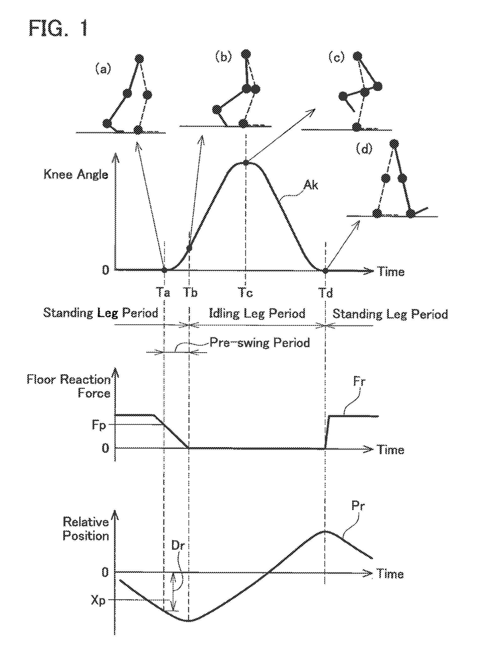
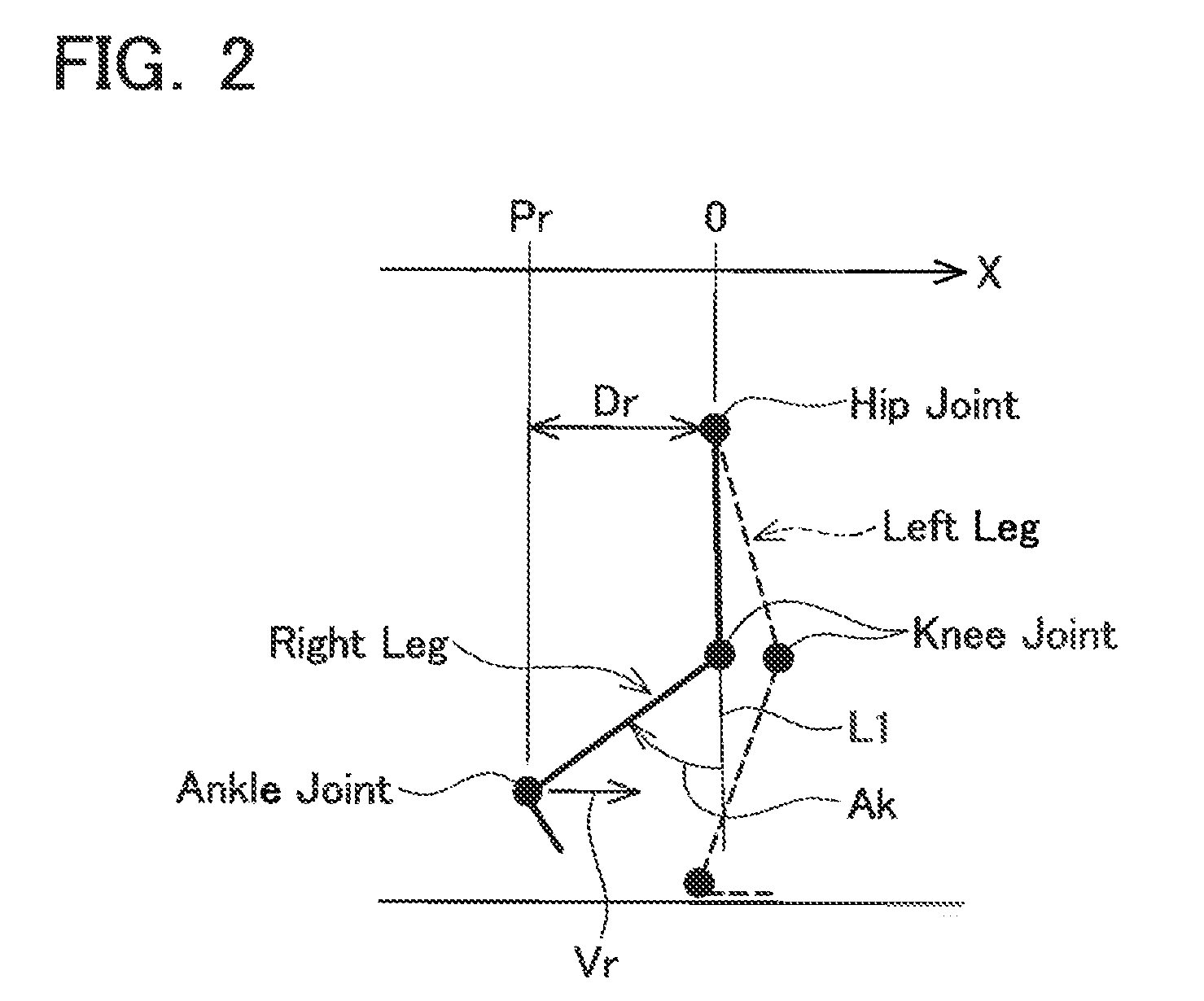
[0023]Before describing a preferred embodiment of the present invention, a motion of a leg during walking will be described. FIG. 1 is a diagram for describing the motion of a first leg during walking. The graph labeled with reference symbol. Ak shows time change in an angle of a knee joint (knee angle) Ak of the first leg. The graph labeled with reference symbol Fr shows time change in a floor reaction force Fr received by a foot of the first leg. Reference symbol Pr indicates the time change in the relative position of the foot of the first leg with respect to a hip. Reference symbol Dr indicates a distance in a horizontal direction between the foot of the first leg and the hip. Reference symbol Xp indicates a reference for judging the state of the first leg (predetermined relative position). The predetermined position Xp is described hereinafter. In the description given below, the right leg of the user corresponds to the first leg and the left leg corresponds to the second leg. ...


PUM


Abstract

To provide a walking assist device which can apply torque to a knee joint at a suitable timing. A walking assist device includes an actuator, a reaction force sensor and an angle sensor. The walking assist device is fitted to a user's leg. The actuator is able to apply torque to a knee joint of one leg of the user. The reaction force sensor detects a reaction force that the foot of the one leg receives from the floor. The angle sensor detects a hip joint angle of the one leg around a pitch axis. The walking assist device specifies a timing to start applying the torque to the knee joint in a direction that swings the lower leg backward, based on the detected reaction force and the detected hip joint angle.

Description

TECHNICAL FIELD[0001]The present invention relates to a walking assist device which assists a walking motion of a user.BACKGROUND ART[0002]A walking assist device which assists a walking motion by applying torque to a leg joint of a user has been researched. Patent document 1, for example, discloses a walking assist device which assists walking of a user having one leg that does not move freely. Hereinafter, in the present specification, a leg which the user can move freely is called a “sound leg” and a leg in which the user cannot freely move at least one joint is called an “affected leg”. Furthermore, in the present specification, the portion from the knee to the ankle is called “lower leg”. The walking assist device disclosed in Patent document 1 measures a pattern of motion of a sound leg with a sensor, and applies torque to a joint of an affected leg in such a manner that the pattern of motion of the affected leg follows the pattern of motion of the sound leg.[0003]Patent docum...

Claims


Application Information

Patent Timeline
IPC IPC(8): A61H1/02
CPCA61H3/00A61H2201/0176A61H2201/1215A61H2201/5061A61H2201/5069A61H2201/5079A61H2205/102A61H2201/165A61H2003/007
Inventor NAKASHIMA, ISSEIMANABE, SHUHEI
Owner TOYOTA JIDOSHA KK
Why Eureka
Try Eureka