Medical needle

a needle and needle technology, applied in the field of needles, can solve problems such as discomfort for users, and achieve the effect of reducing discomfort for users

Pending Publication Date: 2021-10-28
KAWASUMI LABORITORIES INC
View PDF12 Cites 0 Cited by
  • Summary
  • Abstract
  • Description
  • Claims
  • Application Information

AI Technical Summary

Benefits of technology

[0007]The second object is to alleviate a user's discomfort feeling caused when a needle tip is accommodated in a case.

Problems solved by technology

In this case, the needle or a needle connection portion accommodated in the case energetically comes into contact with an inner face of the case, and accordingly a relatively strong impact and a collision noise occur, so that a user may have a discomfort feeling.

Method used


Image

  • Medical needle
  • Medical needle
  • Medical needle

Examples


embodiment 1-1

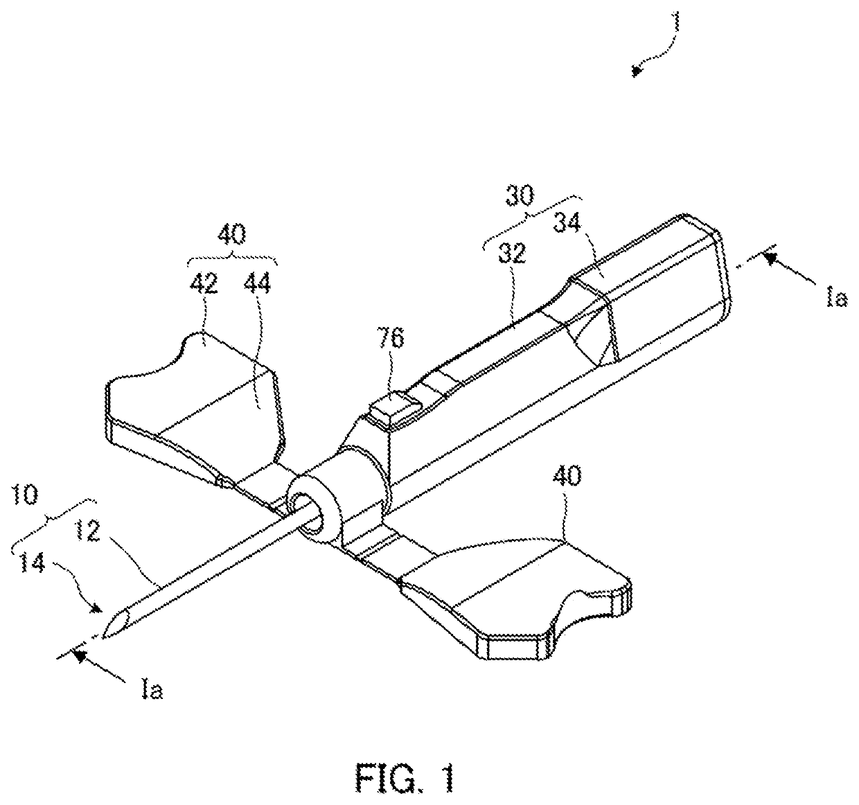
[0025]FIG. 1 to FIG. 3 illustrate configurations of a medical needle 1 according to embodiment 1-1 of the present invention.

[0026]The medical needle 1 is e.g. a winged needle that is used so as to be fixed while piercing a patient's skin during blood collection, blood transfusion, fluid infusion, or the like.

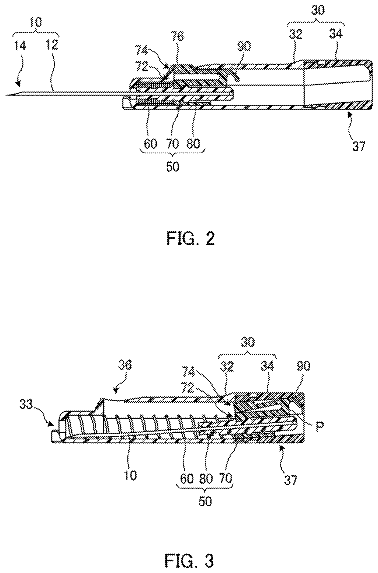
[0027]As illustrated in FIG. 1 to FIG. 3, the medical needle 1 according to embodiment 1-1 includes a needle portion 10 having a needle tip 14, a case 30 capable of accommodating the needle portion 10, wing portions 40 provided on a distal end portion of the case 30, a movement mechanism 50 for moving the needle portion 10 to put the needle portion 10 into the case 30, and a movement restricting portion 37 that restricts the movement of the needle portion 10 accommodated in the case 30.

[0028]In the following explanation, the position where the needle tip 14 protrudes from the case 30 by a predetermined length as illustrated in FIG. 2 is referred to as a “first position”, and a p...

embodiment 1-2

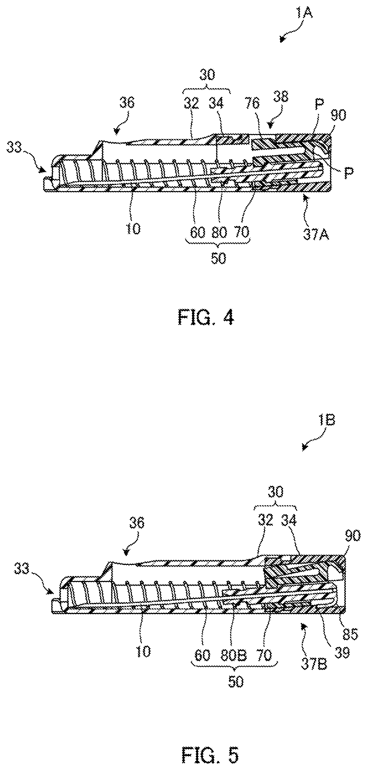
[0070]FIG. 6 is a sectional view illustrating a medical needle 1C according to embodiment 1-2. In the medical needle 1C according to embodiment 1-2, the movement restricting portion restricts the movement of the needle tip 14 in the opposite direction only by engagement. Note that configurations other than configurations to be explained in detail below are the same as in embodiment 1-1, and detailed explanation of the same configurations is omitted.

[0071]In the medical needle 1C, the second engagement portion 38 is provided on the inner face of the concave portion of the cover portion 34, but the inner face of the cover portion 34 is not sloped, and is parallel to the moving direction of the needle portion 10. When the needle portion 10 is accommodated in the case 30, a movement restricting portion 37C of the medical needle 1C restricts the movement of the needle tip 14 in the opposite direction by engaging the convex portion 76 of the movement mechanism 50 with the second engagemen...

embodiment 2-1

[0078]FIG. 7 to FIG. 11 illustrate configurations of a medical needle 1001 according to embodiment 2-1 of the present invention.

[0079]The medical needle 1001 is e.g. a winged needle that is used so as to be fixed while piercing a patient's skin during blood collection, blood transfusion, fluid infusion, or the like.

[0080]As illustrated in FIG. 7 to FIG. 11, the medical needle 1001 according to embodiment 2-1 includes a needle portion 1010 having a needle tip 1014, a case 1030 capable of accommodating the needle portion 1010, wing portions 1040 provided on the case 1030, and a movement mechanism 1050 for moving the needle portion 1010 to put the needle portion 1010 into the case 1030.

[0081]In the following explanation, the position where the needle tip 1014 protrudes from the case 1030 by a predetermined length as illustrated in FIG. 8 is referred to as a “first position”, and a position where the needle tip 1014 is accommodated in the case 1030 as illustrated in FIG. 9 is referred t...


PUM


Abstract

A medical needle includes a needle portion (10) having a needle tip on a distal end, a case (30) configured to be capable of accommodating the needle portion that can be exposed from the distal end side, a movement mechanism (50) for moving the needle portion inside the case, and a movement restricting portion (37) that restricts the needle tip accommodated in the case from moving in a direction opposite to a moving direction of the needle portion. The movement restricting portion maintains the needle tip accommodated in the case such that the needle tip can come into contact with an inner face of the case to restrict the movement of the needle tip in the opposite direction.

Description

CROSS REFERENCE TO RELATED APPLICATIONS[0001]This application claims priority under 35 U.S.C. 119 to U.S. provisional patent applications 63 / 014,541 and 63 / 014,528, filed April. 23, 2020. The entire teachings of the above application are incorporated herein by reference.TECHNICAL FIELD[0002]The present invention relates to a medical needle.BACKGROUND ART[0003]As a medical needle used for blood collection, blood transfusion, fluid infusion, or the like, a medical needle in which a spring member is disposed inside a cylindrical case has been conventionally known (e.g. see JP 2002-539897 W). According to the conventional medical needle, a needle tip exposed from a case can be accommodated in a case by an action of a spring member. Thus, it is possible to prevent occurrence of an accident that one who uses the medical needle (including a medical worker and a patient, who are hereinafter referred to as a user) accidentally sticks a used medical needle into oneself (so-called erroneous st...

Claims


Application Information

Patent Timeline
Patent Type & Authority Applications(United States)
IPC IPC(8): A61M5/32
CPCA61M5/3245A61M25/0637A61M2005/3249A61M5/3257A61M2005/3247
Inventor TAMAI, YUSUKE
Owner KAWASUMI LABORITORIES INC
Why Eureka
Try Eureka