Tilt-type steering apparatus

a steering apparatus and tilting technology, applied in mechanical devices, shock absorbers, transportation and packaging, etc., can solve the problems of excessively rapid rotation of the tilting lever b>33/b>, driver operating the tilting lever b>, and may feel uncomfortable or unpleasant, etc., to achieve sufficient damper and attenuation effects, small size, and reduced axial size of the expandable mechanism.

Active Publication Date: 2014-11-20
NSK LTD
View PDF9 Cites 3 Cited by
  • Summary
  • Abstract
  • Description
  • Claims
  • Application Information

AI Technical Summary

Benefits of technology

[0025]According to the above-described tilt-type steering apparatus, it is possible to prevent the tilt lever from being rapidly rotated when rotating the tilt lever so as to position the steering wheel. That is, the telescopic damper provided between the lever-side engaging portion which rotates together with the tilt lever and the cam-side engaging part provided on the driven cam serves as a resistance against the rotation of the tilt lever in the direction of enabling the position of the steering wheel to be adjusted. Therefore, even with the distal ends of the respective convex portions of the driving cam surface and the driven cam surface of the expandable mechanism being pressed against the counterpart cam surface, the momentum of reducing the axial size of the expandable mechanism is weakened. As a result, it is possible to prevent a driver operating the tilt lever that rotates the driving-side cam from feeling unpleasant. The telescopic damper can realize the sufficient damper and attenuation effects with a small size. Also, even when a mounting space is limited for layout reasons, the telescopic damper can be incorporated into the tilt-type steering apparatus to sufficiently prevent the unpleasant feeling.
[0026]The telescopic damper is arranged such that it is extended or shortened only when the tilt lever is rotated. That is, in a state in which the tilt lever is rotated to allow an adjustment of a height position of the steering wheel, even if the steering column is tilted so as to adjust the height position of the steering wheel, the distance between the lever-side engaging portion and the cam-side engaging part does not change Therefore, since the telescopic damper is not extended or shortened as the steering column is tilted, the telescopic damper does not function as a resistance against the height position adjustment of the steering wheel, so that it is possible to perform the height position adjustment more smoothly.
[0027]When the hollow cylinder part having a distal end with an opening is arranged at the lower side, the grease interposed between the inner periphery of the cylinder part and the outer periphery of the damper rod is difficult to leak out. Therefore, it is possible to keep sufficient amount of grease between the peripheries for a long time, and to keep the effect of preventing the unpleasant for a long time.
[0028]By sufficiently providing an area in which the inner periphery of the cylinder part and the outer periphery of the damper rod face each other, it is possible to obtain sufficient damper effect with a smaller telescopic damper.
[0029]When the kinematic viscosity of the base oil of the grease is controlled to be within a range of 500 to 50000 mm2 / s (40° C.), it is possible to effectively prevent the unpleasant feeling. In particular, when the kinematic viscosity of the base oil of the grease is controlled within a range of 5000 to 20000 mm2 / s (40° C.), it is possible to sufficiently prevent the unpleasant feeling even if the inner periphery of the cylinder part and the outer periphery of the damper rod are configured as simple cylindrical surfaces.
[0030]When the linear expansion coefficient of the radially inner side material forming the damper rod is greater than the linear expansion coefficient of the radially outer side material forming the cylinder part, it is possible to suppress a change in damper performance due to a temperature change to be small. That is, while suppressing the change in damper performance to be small, it is possible to suppress a variation of force required to operate the tilt lever to be small, irrespective of the temperature change. As a result, it is possible to further reduce discomfort feeling, which may be given to the driver operating the tilt lever.

Problems solved by technology

However, as the cam device 32 is used, when the tilt lever 33 is rotated in a predetermined direction (for example, a downward direction) so as to position the steering wheel 1, the tilt lever 33 may be excessively rapidly rotated.
As a result, the tilt lever 33 having the base end part to which the driving cam 30 is fixed is rapidly rotated in the predetermined direction, so that a driver operating the tilt lever 33 may feel uncomfortable or unpleasant, or an unpleasant collision noise may be generated.

Method used


Image

  • Tilt-type steering apparatus
  • Tilt-type steering apparatus
  • Tilt-type steering apparatus

Examples


Embodiment Construction

[0055]First, a related embodiment of the invention will be described with reference to FIGS. 12 to 20.

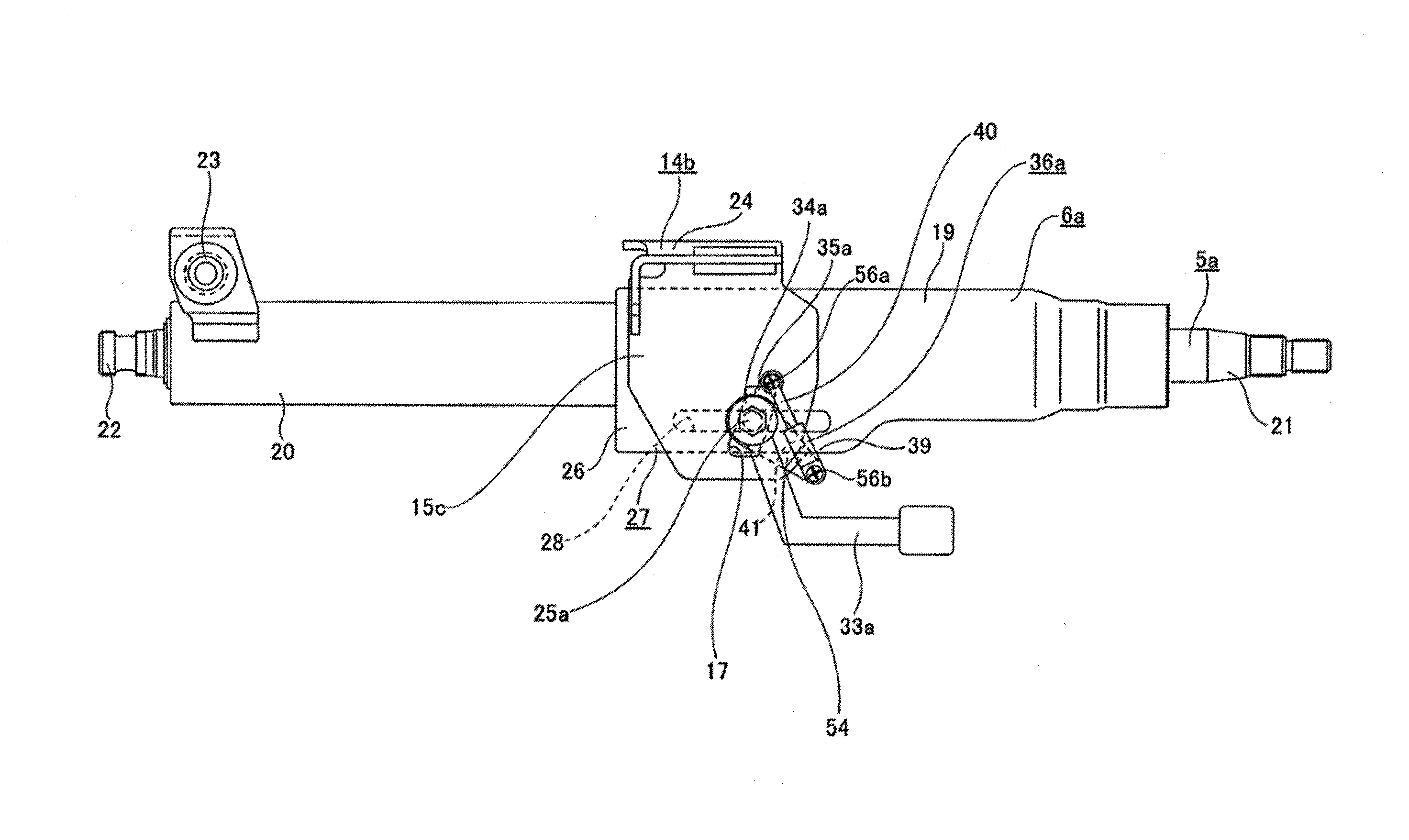
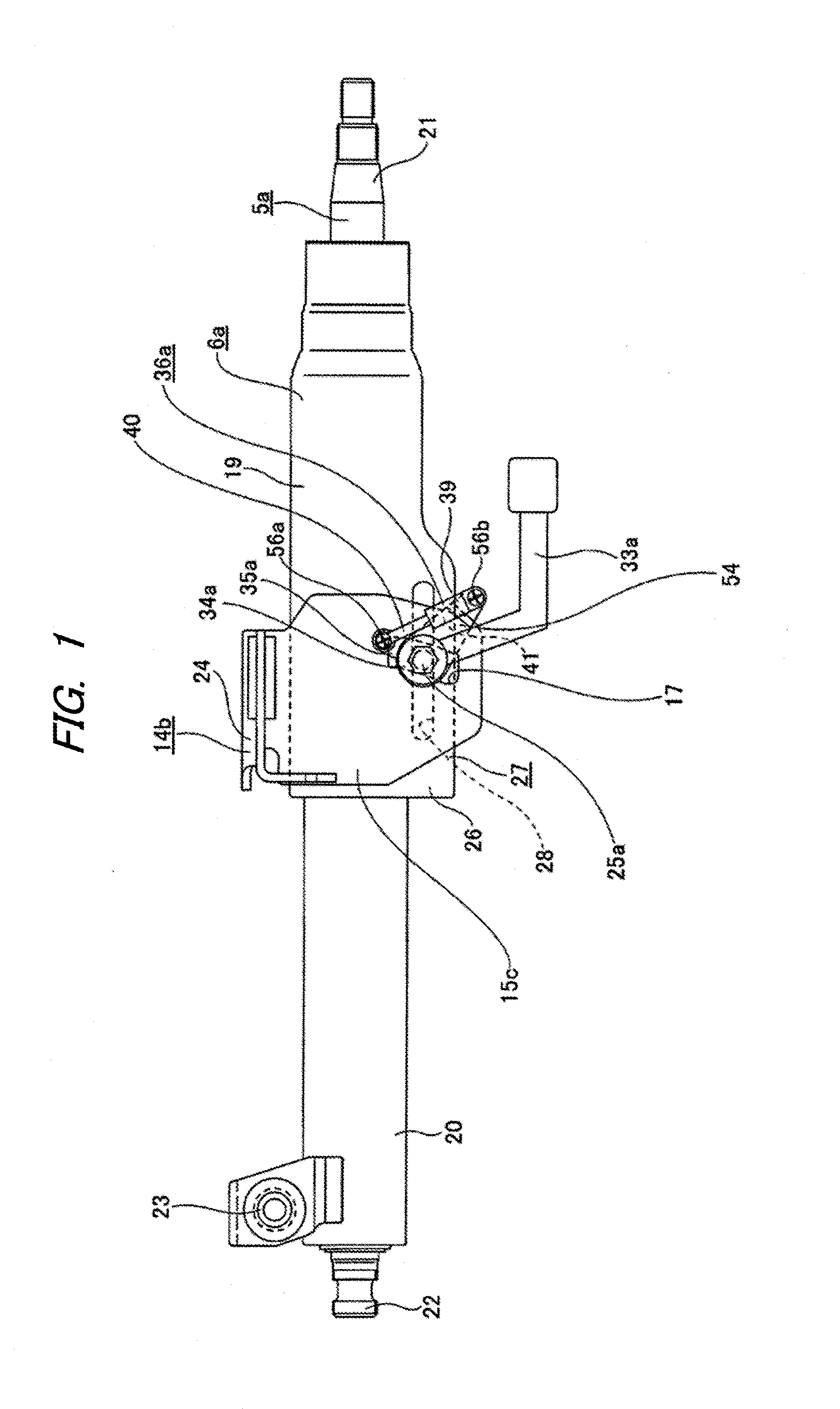
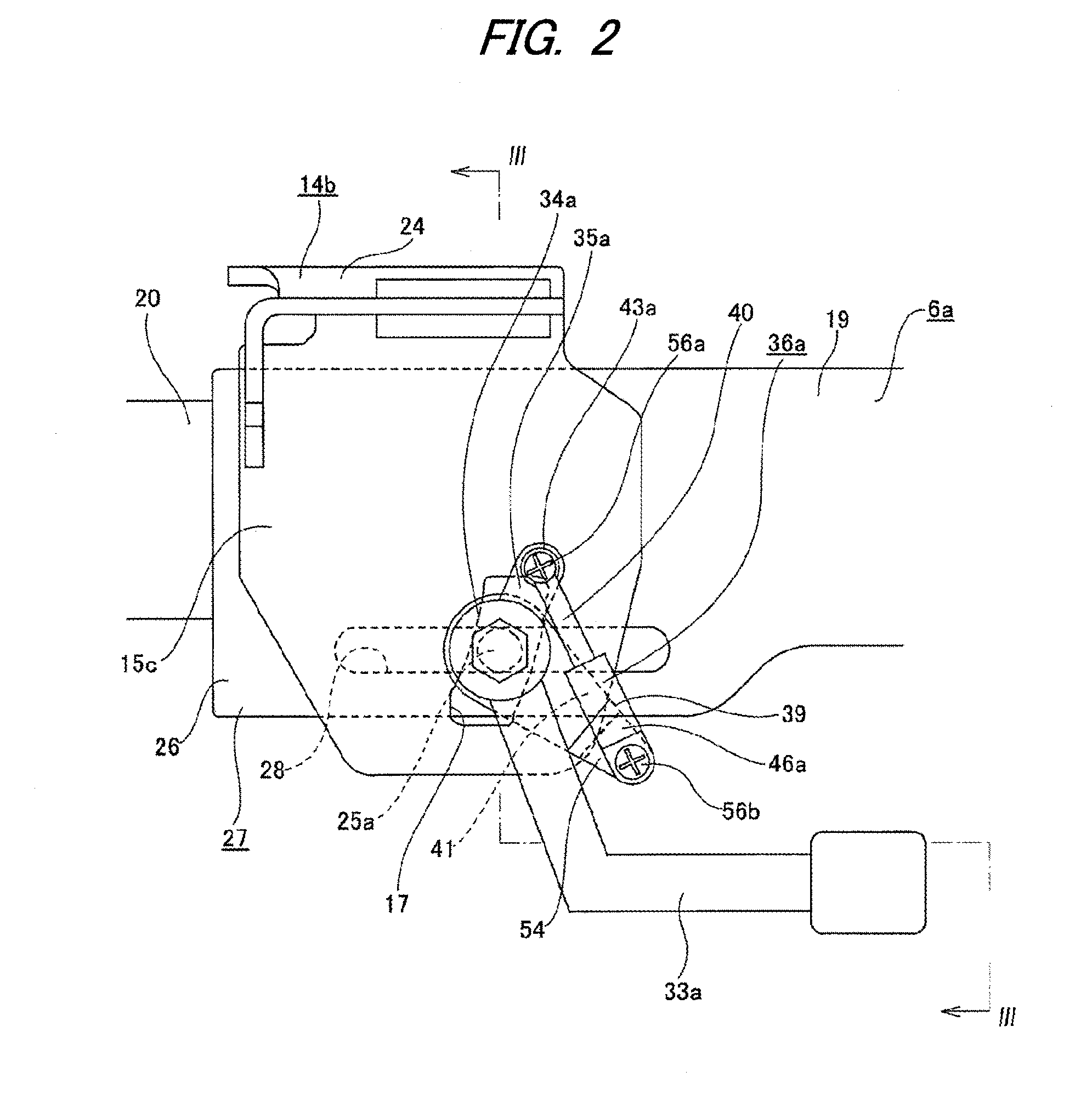
[0056]In a tilt-type steering apparatus of the related embodiment, a base end part of a tilt lever 33 is provided with a boss part 34. An outer periphery of the boss part 34 is formed with a protrusion 35 (an example of the lever-side engaging portion), which protrudes from the outer periphery of the boss part 34 in a radially outer direction, at a part that is spaced from the tilt lever 33 in a circumferential direction. Hence, the protrusion 35 is rotated about a tilt rod 25 together with the tilt lever 33. A telescopic damper 36 is arranged to extend between and connect a distal end of the protrusion 35 and an outer surface of a support plate portion 15c of a support bracket 14b. As shown in FIGS. 19A and 19B, a distal end of the protrusion 35 is formed with a circular connection hole 37 to which one end portion of the telescopic damper 36 is connected. A lower half part of the s...


PUM


Abstract

A tilt-type steering apparatus includes a tilt lever, an expandable mechanism having a driving cam rotated by the tilt lever and a driven cam engaged with the driving cam, and a telescopic damper arranged to apply resistance against the rotation of the tilt lever in a direction allowing a position of a steering wheel to be adjusted. The telescopic damper is provided between a lever-side engaging portion which rotates together with the tilt lever and a cam-side engaging part of the driven cam.

Description

TECHNICAL FIELD [0001]The invention relates to a tilt-type steering apparatus configured to adjust a height position of a steering wheel in conformity to a physique of a driver or a driving posture.BACKGROUND ART [0002]A tilt-type steering apparatus is widely known. First, a first conventional example of a vehicle steering apparatus will be described based on the disclosure of Patent Document 1. As shown in FIG. 7, a vehicle steering apparatus is configured such that rotation of a steering wheel 1 is transmitted to an input shaft 3 of a steering gear unit 2, a pair of left and right tie-rods 4, 4 is pushed / pulled in connection with rotation of the input shaft 3 and a steering angle is thus applied to front wheels. The steering wheel 1 is supported and fixed to a rear end portion of a steering shaft 5. The steering shaft 5 is rotatably supported by a cylindrical steering column 6 with being axially inserted into the steering column 6. A front end portion of the steering shaft 5 is co...

Claims


Application Information

Patent Timeline
Patent Type & Authority Applications(United States)
IPC IPC(8): B62D1/187
CPCB62D1/187B62D1/184F16F9/16F16F9/103
Inventor MORIYAMA, SEIICHI
Owner NSK LTD
Why Eureka
Try Eureka