Steering system

a steering system and steering wheel technology, applied in the direction of mechanical steering, electrical steering, vehicle components, etc., can solve the problems of driver discomfort, steering wheel rotation, etc., and achieve the effect of reducing the discomfort of the driver

Pending Publication Date: 2021-12-23
SPIKE BREWING LLC +2
View PDF3 Cites 1 Cited by
  • Summary
  • Abstract
  • Description
  • Claims
  • Application Information

AI Technical Summary

Benefits of technology

[0018]With the steering system according to the aspect of the disclosure, it is possible to decrease a driver's feeling of discomfort in the case where automatic rotation of the steering wheel is hindered and then the hindered automatic rotation is released while the adjustment process of automatically adjusting the rotational position of the steering wheel is being performed.

Problems solved by technology

Accordingly, when a certain external force is applied to the steering wheel in a state in which the vehicle is powered off, there is a likelihood that the steering wheel may rotate.
Accordingly, when the reason for hindering the automatic rotation of the steering wheel is resolved, the steering wheel may rotate suddenly to the target steering angle and a driver may have a feeling of discomfort due to the sudden rotation of the steering wheel.

Method used


Image

  • Steering system
  • Steering system
  • Steering system

Examples


first embodiment

Advantages of First Embodiment

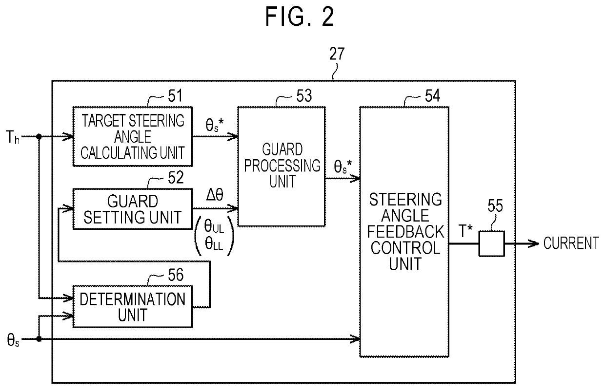
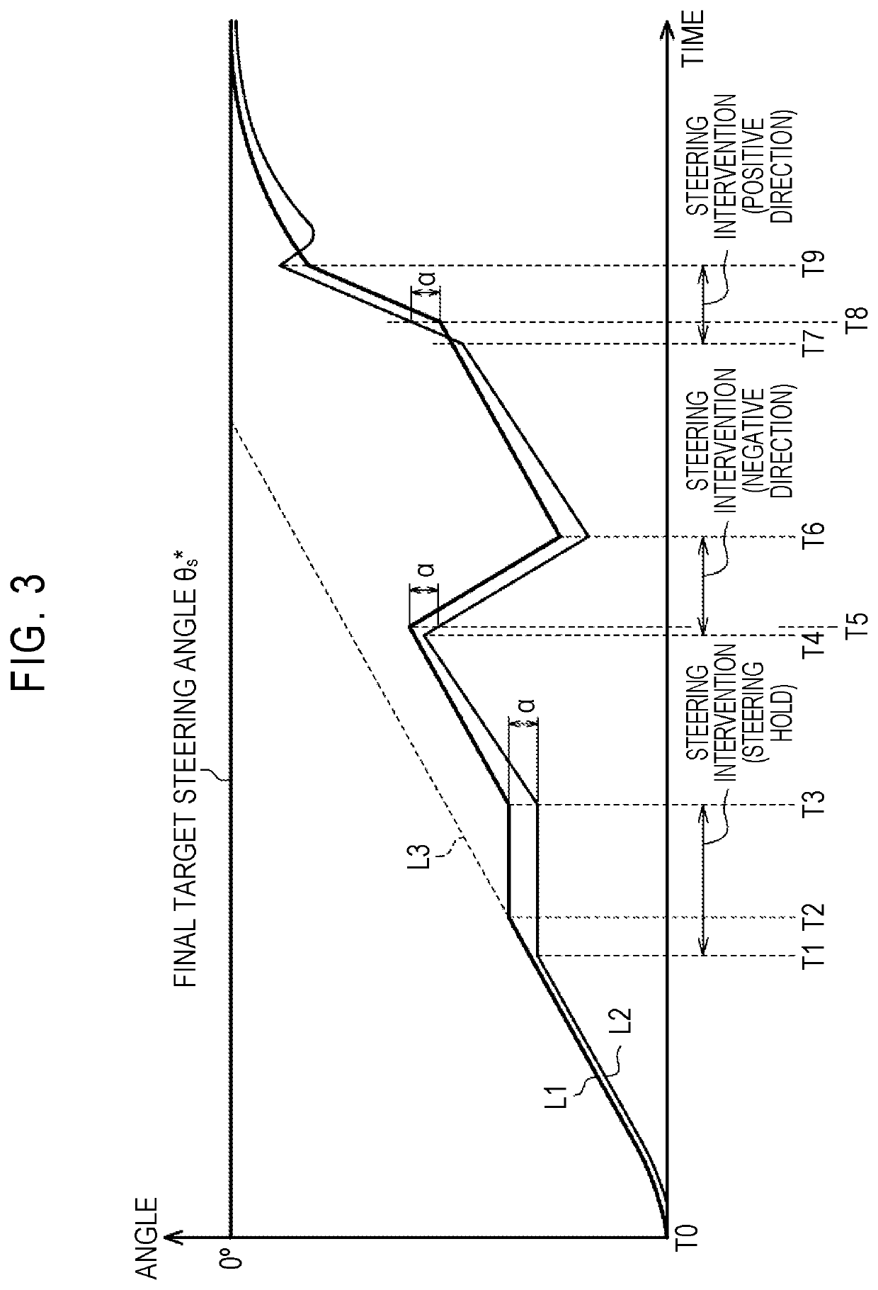
[0070]Accordingly, according to the first embodiment, the following advantages can be achieved. (1) In the case where the automatic rotation of the steering wheel 11 is hindered while the adjustment process of automatically adjusting the rotational position of the steering wheel 11 is being performed, the value of the target steering angle θs* is limited such that the absolute value of the difference between the target steering angle θs* and the steering angle θs is not greater than the set value α. The set value α is set based on the viewpoint of curbing an increase of the difference between the target steering angle and the steering angle, that is, the viewpoint of curbing sudden change of the steering angle θs when a reason for hindering the automatic rotation of the steering wheel 11 is resolved. Accordingly, in the case where the automatic rotation of the steering wheel 11 is hindered while the adjustment process of adjusting the rotational positio...

second embodiment

[0071]A steering system according to a second embodiment of the disclosure will be described below. This embodiment basically has the same configuration as the first embodiment illustrated in FIGS. 1 and 2. This embodiment may be embodied in combination with the first embodiment.

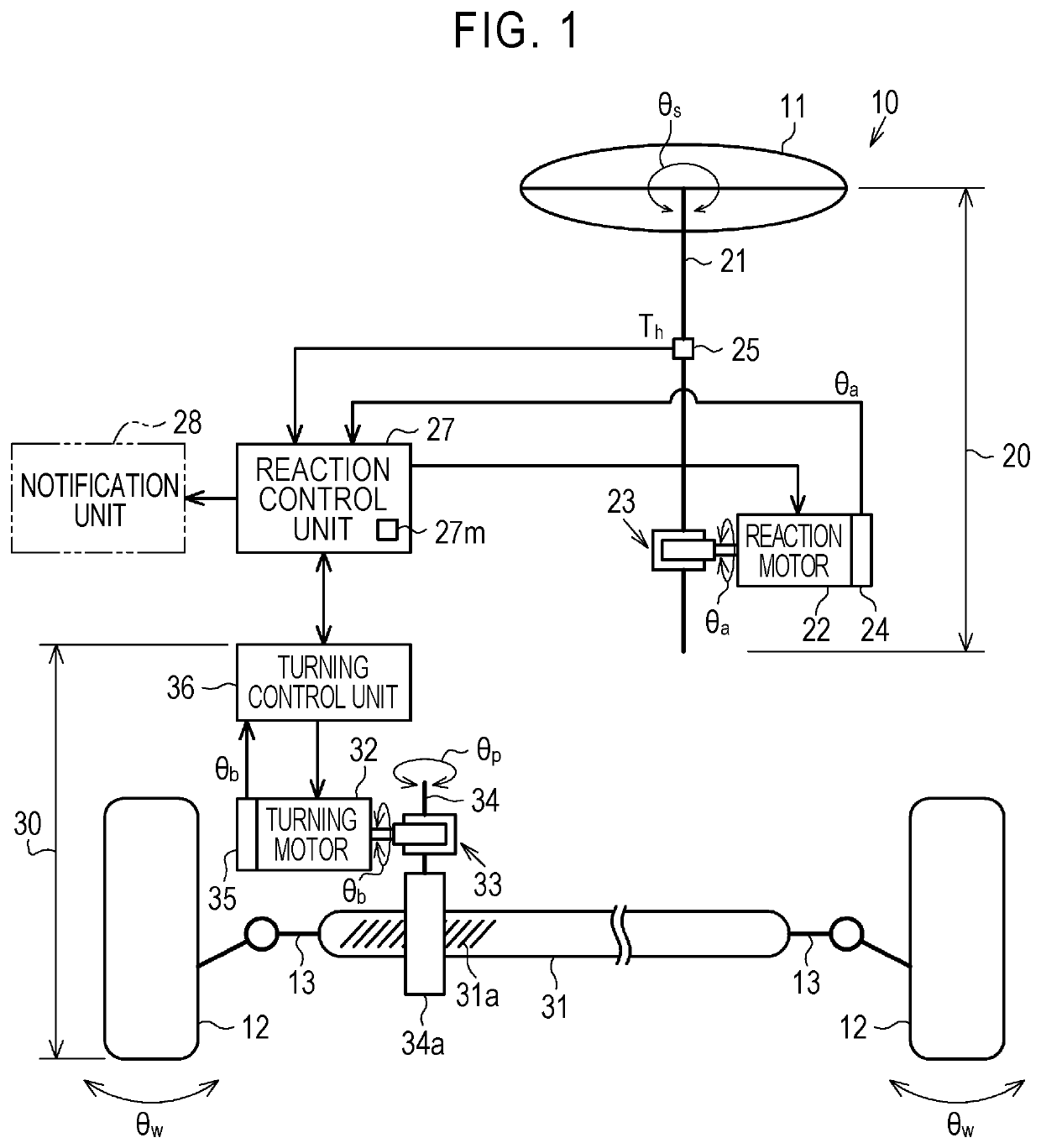
[0072]As illustrated in FIG. 4, the reaction unit 20 includes a stopper mechanism 40. The stopper mechanism 40 is provided to limit the steering angle θs of the steering wheel 11. The stopper mechanism 40 restricts rotation of the steering wheel 11 over one turn (360°). FIG. 4 is a rearview of the steering wheel 11.

[0073]The stopper mechanism 40 includes a first restriction member 41 and a second restriction member 42. The first restriction member 41 is fixed to a steering column 43 that supports the steering shaft 21 at the vehicle body. The first restriction member 41 extends in a radial direction of the steering shaft 21. The first restriction member 41 includes a first restriction surface 41a and a secon...

third embodiment

[0092]A steering system according to a third embodiment of the disclosure will be described below. This embodiment basically has the same configuration as that of the first embodiment illustrated in FIG. 1, and this embodiment is different from the first embodiment in the configuration of the reaction control unit 27. This embodiment may be embodied in combination with the second embodiment.

[0093]As illustrated in FIG. 5, the reaction control unit 27 includes a first control unit 27a, a second control unit 27b, a switch 27c, a power supply control unit 27d, and a flag setting circuit 27e. The first control unit 27a is a unit that performs normal reaction control for generating a steering reaction force corresponding to the steering torque Th through drive control of the reaction motor 22. The first control unit 27a includes a target steering reaction force calculating unit 61, an axial force calculating unit 62, and a subtractor 63.

[0094]The target steering reaction force calculatin...


PUM


Abstract

A steering system includes a steering shaft; a motor configured to generate a torque applied to the steering shaft; and a control unit configured to control the motor. The control unit has a function of performing steering angle feedback control for causing a steering angle that is a rotation angle of a steering wheel to reach a target steering angle that is set based on a point of view of adjusting a rotational position of the steering wheel, as an adjustment process of adjusting the rotational position of the steering wheel. The control unit is configured to set a limit value for limiting a change range of the target steering angle with respect to the steering angle at each moment in a period in which automatic rotation of the steering wheel is hindered in a case where the automatic rotation is hindered while the adjustment process is being performed.

Description

CROSS-REFERENCE TO RELATED APPLICATION[0001]This application claims priority to Japanese Patent Application No. 2020-105196 filed on Jun. 18, 2020, incorporated herein by reference in its entirety.BACKGROUND1. Technical Field[0002]The disclosure relates to a steering system of a vehicle.2. Description of Related Art[0003]There has been a so-called steer-by-wire steering system in which transmission of power between a steering wheel and turning wheels is cut off. Such a steering system includes a reaction mechanism including a reaction motor that is a source of a steering reaction force that is applied to a steering shaft and a turning mechanism including a turning motor that is a source of a turning force for turning the turning wheels. When a vehicle is traveling, a control device for the steering system generates a steering reaction force through power supply control for the reaction motor and turns the turning wheels through power supply control for the turning motor.[0004]In suc...

Claims


Application Information

Patent Timeline
Patent Type & Authority Applications(United States)
IPC IPC(8): B62D6/00B62D5/04B62D5/00
CPCB62D6/008B62D5/006B62D5/0466B62D5/046B62D15/0205
Inventor KAKIMOTO, YUSUKEUCHINO, YOSHIYUKISHIBATA, KENJISATO, TAKAFUMI
Owner SPIKE BREWING LLC
Why Eureka
Try Eureka