Eureka AIR delivers breakthrough ideas for toughest innovation challenges, trusted by R&D personnel around the world.

Electric rotating machine

Inactive Publication Date: 2012-09-13
HITACHI LTD
View PDF4 Cites 8 Cited by
  • Summary
  • Abstract
  • Description
  • Claims
  • Application Information

AI Technical Summary

Benefits of technology

[0013]The object of this invention, which has been made to solve the above mentioned problem, is to provide an electric rotating machine which is free from the procedure of selecting different preset neutral current values for different types of machines, which can detect a ground fault in a phase coil of the armature winding without suffering any erroneous operation, and which can detect a ground fault in a phase coil of the armature winding even when electric brake is being actuated.
[0016]This invention, which has been designed as described above, has following advantages.
[0018]Further, the electric rotating machine according to this invention can detect a coil ground fault even when electric braking is being actuated.

Problems solved by technology

Accordingly, there was a problem that the detection of a ground fault by these methods is difficult.

Method used


Image

  • Electric rotating machine
  • Electric rotating machine
  • Electric rotating machine

Examples


embodiment 1

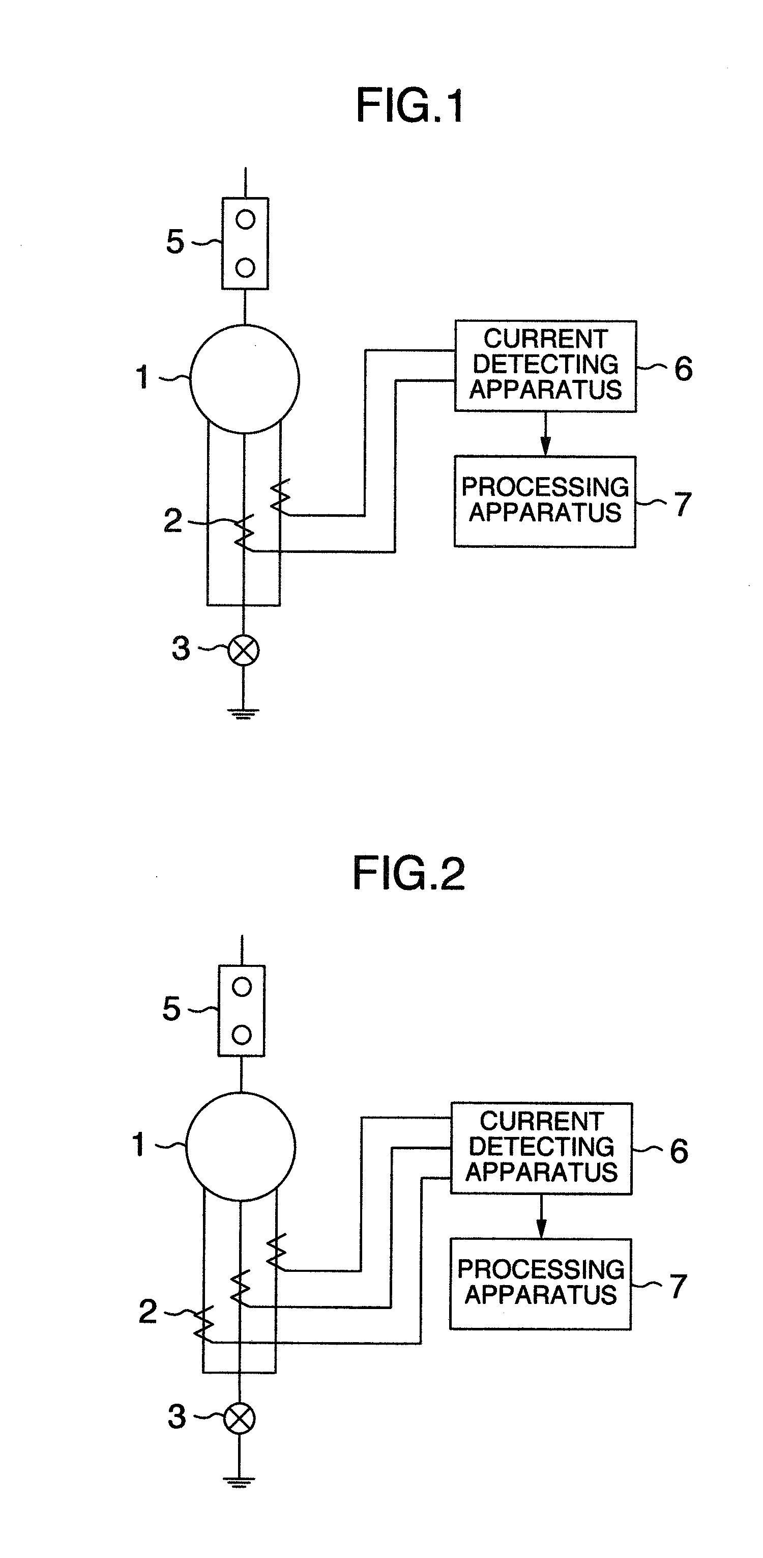
[0035]FIG. 1 is a wiring diagram for an eclectic rotating machine as a first embodiment of this invention. In the armature winding of an electric rotating machine 1, the neutral of the three phase coils is grounded through a disconnector 3. Current measuring apparatuses 2 are furnished for the two phase coils of the three-phase armature winding so as to measure currents through the two phase coils. The measured currents for the two phases are detected by a current detecting apparatus 6. A processing unit 7 compares the harmonic components of the two phase currents with each other, and it is decided that a ground fault has occurred in one of the two phase coils if the harmonic components differ from each other.

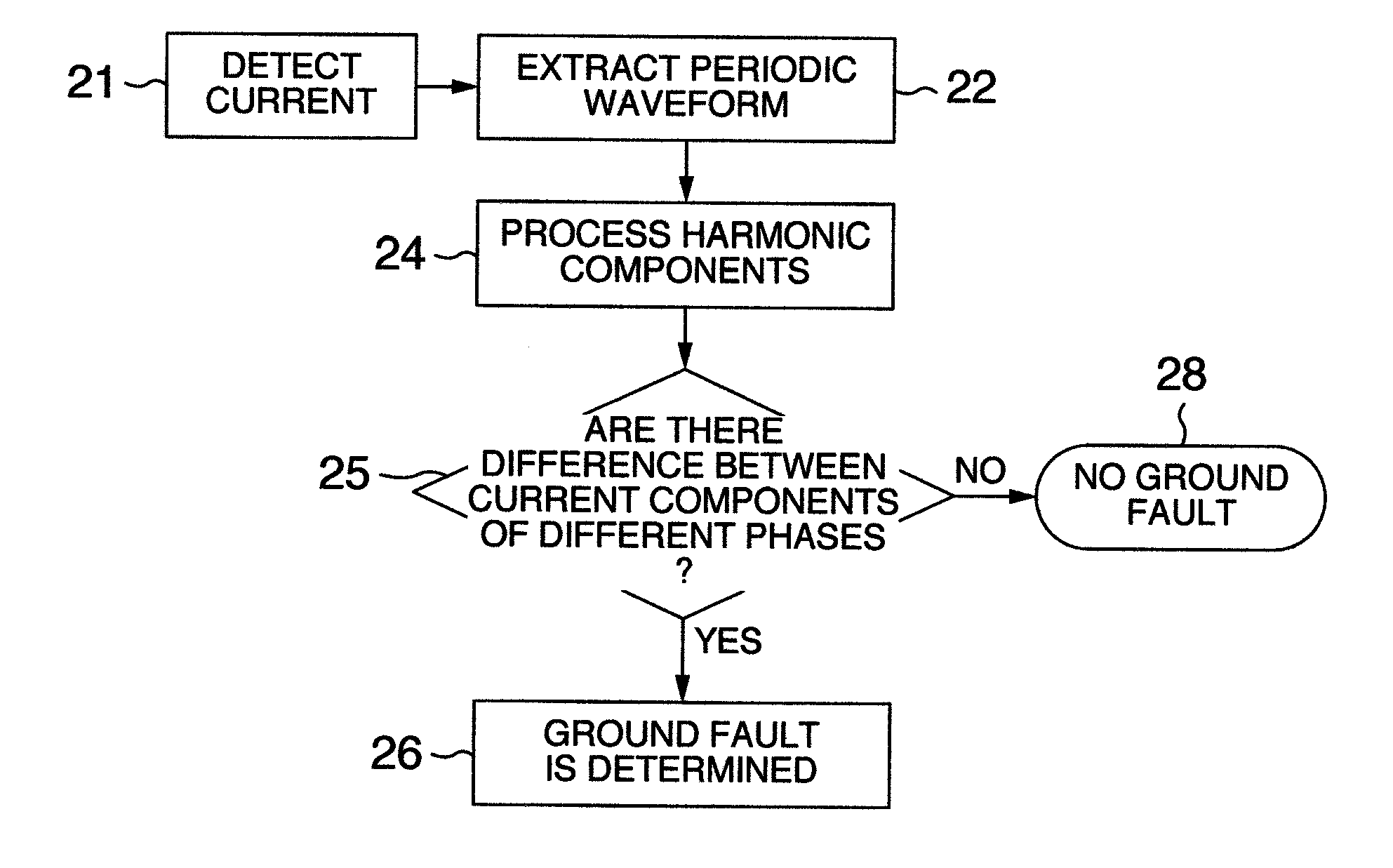
[0036]FIG. 10 shows the flow of an operation for detecting a ground fault in the first embodiment of this invention. In Step 21, current detection is performed by means of the current detecting apparatus 6. In Step 22, periodic waveforms are extracted on the basis of the detect...

embodiment 2

[0044]FIG. 2 is a wiring diagram for an eclectic rotating machine as a second embodiment of this invention. In the first embodiment described above, two phase currents are compared with each other. However, three phase currents may be measured to detect a ground fault in the armature winding.

embodiment 3

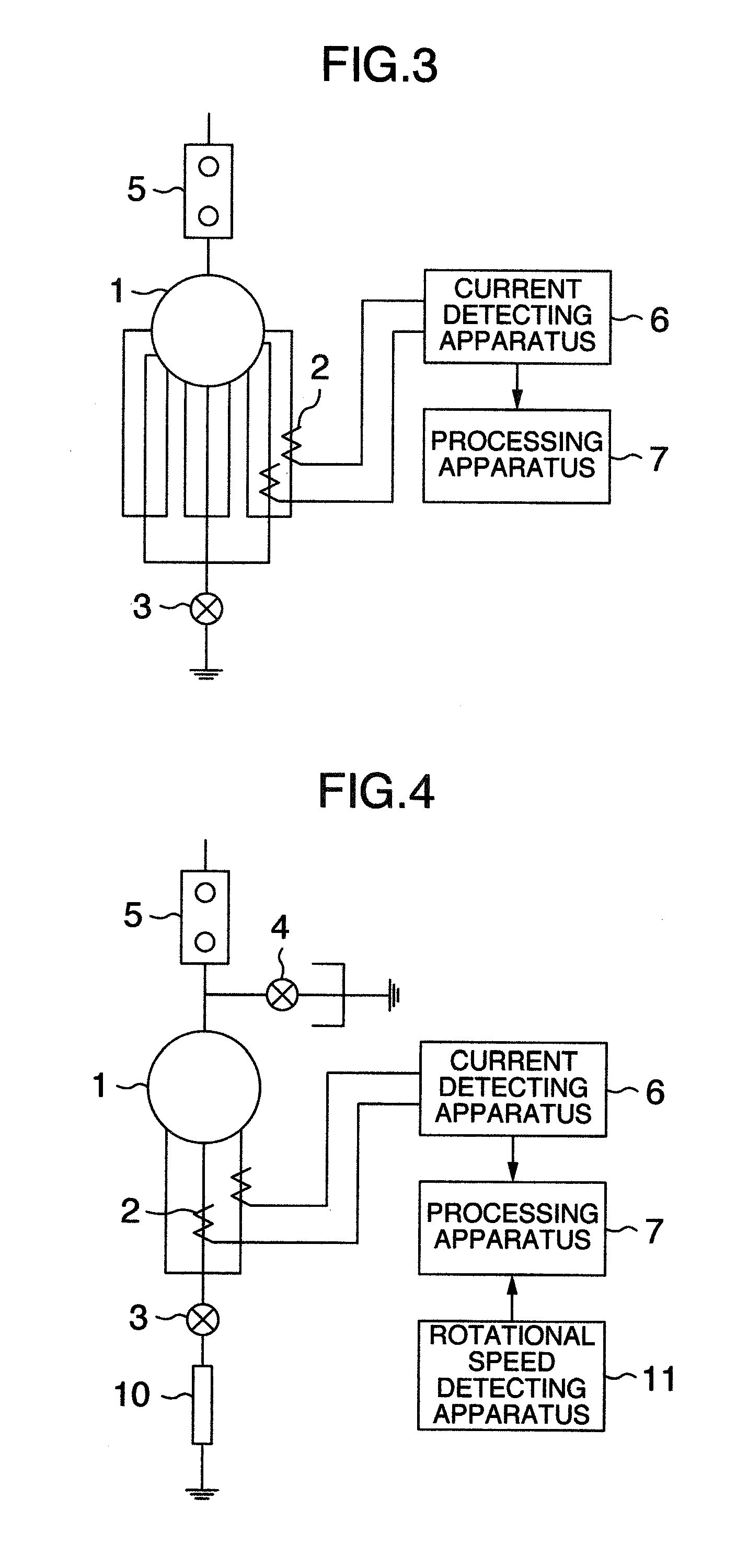
[0045]FIG. 3 is a wiring diagram for an eclectic rotating machine as a third embodiment of this invention. In this embodiment, an electric rotating machine 1 includes three-phase coils in the armature winding, each phase coil consisting of three parallel circuits. The two parallel circuits of a phase coil are furnished with current measuring apparatuses 2, and one of the parallel circuits of another phase coil may also be furnished with a current measuring apparatus 2 (not shown). A processing apparatus 7 compares the harmonic components of the currents detected in the two parallel circuits of the same phase coil or in one parallel circuit of a phase coil and one parallel circuit of another phase coil, by the current detecting apparatus 6. Then, the processing apparatus 7 decides that a ground fault has occurred in any of the phase coils of the armature winding if the harmonic components in two different parallel circuits differ from each other.

[0046]In a parallel circuit in which a...


PUM


Abstract

This invention aims to provide an electric rotating machine which is free from the procedure of selecting different preset neutral current values for different types of machines, and which can detect a ground fault in a phase coil of the armature winding without suffering any erroneous operation. An electric rotating machine having an armature winding including three phase coils, which has been provided to attain the object of this invention, comprises a grounding resistor connected at a neutral of the armature winding, and current measuring apparatuses furnished for at least two phase coils, wherein phase currents through the phase coils are compared with each other, and the detection of a coil ground fault is determined when harmonic components of the phase currents differ from each other.

Description

[0001]This invention relates to an electric rotating machine which can detect a ground fault occurring in a phase coil of the armature winding and therefore protect itself from the ground fault.BACKGROUND OF THE INVENTION[0002]In general, the fact that a ground fault has occurred in the armature winding of an electric rotating machine is determined by comparing the current through the neutral in the armature winding at the time of the ground fault taking place with a preset value or a modified version of the preset value adjusted depending on the output, etc. FIG. 8 is a wiring diagram for an example of a conventional electric rotating machine capable of detecting a ground fault. In an electric rotating machine 1, the three phase coils of the armature winding are connected together to form a neutral, and the neutral is grounded via a disconnector 3 and a neutral grounding resistor 10. And a current measuring apparatus 2 measures the neutral current. The measured current is then dete...

Claims


Application Information

Patent Timeline
IPC IPC(8): G01R31/14
CPCG01R31/025H02H7/06G01R31/343G01R31/52
Inventor NAKAHARA, AKIHITOOKADA, MASAYUKIKAYUKAWA, SHIGEHIRO
Owner HITACHI LTD
Why Eureka
Eureka Blog
Learn More