Cutting tool including a locking screw and adapter with coolant delivery

a technology of locking screw and adapter, which is applied in the direction of tool workpiece connection, shaping cutter, manufacturing tools, etc., can solve the problems of cutting inserts being susceptible to plastic deformation cutting inserts being damaged,

Active Publication Date: 2012-09-13
KENNAMETAL INC
View PDF0 Cites 33 Cited by
  • Summary
  • Abstract
  • Description
  • Claims
  • Application Information

AI Technical Summary

Problems solved by technology

Heat generated due to the material removal process can be detrimental to the integrity of the cutting insert.
If the heat generated and passed along to the cutting insert causes the temperature to rise above a certain limit, the cutting insert can be susceptible to plastic deformation.
Plastic deformation is detrimental to the cutting insert in that it can result in the failure of the cutting insert.
Such a design restriction has limited the design of the cutter body.

Method used


Image

  • Cutting tool including a locking screw and adapter with coolant delivery
  • Cutting tool including a locking screw and adapter with coolant delivery
  • Cutting tool including a locking screw and adapter with coolant delivery

Examples


Embodiment Construction

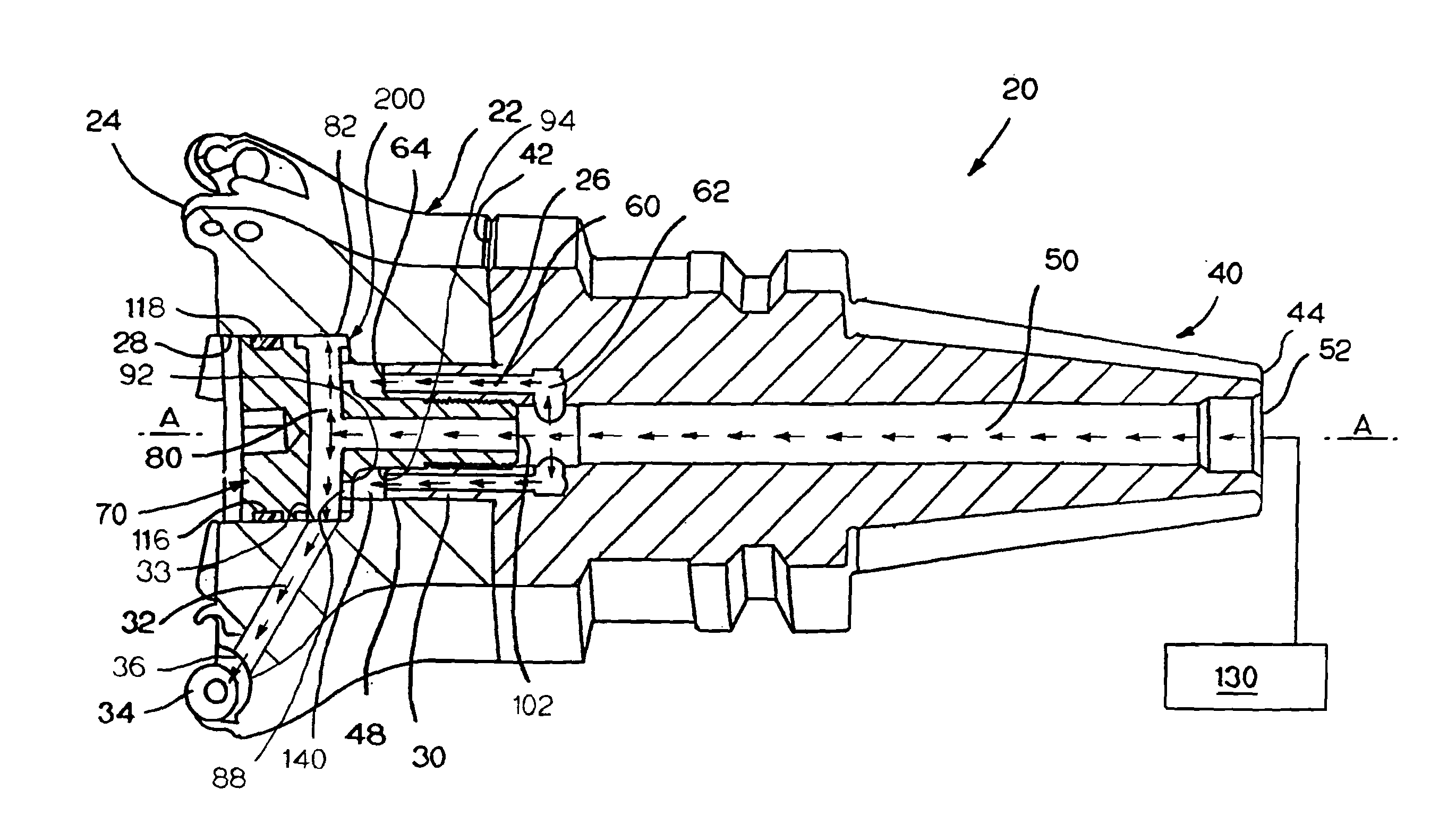
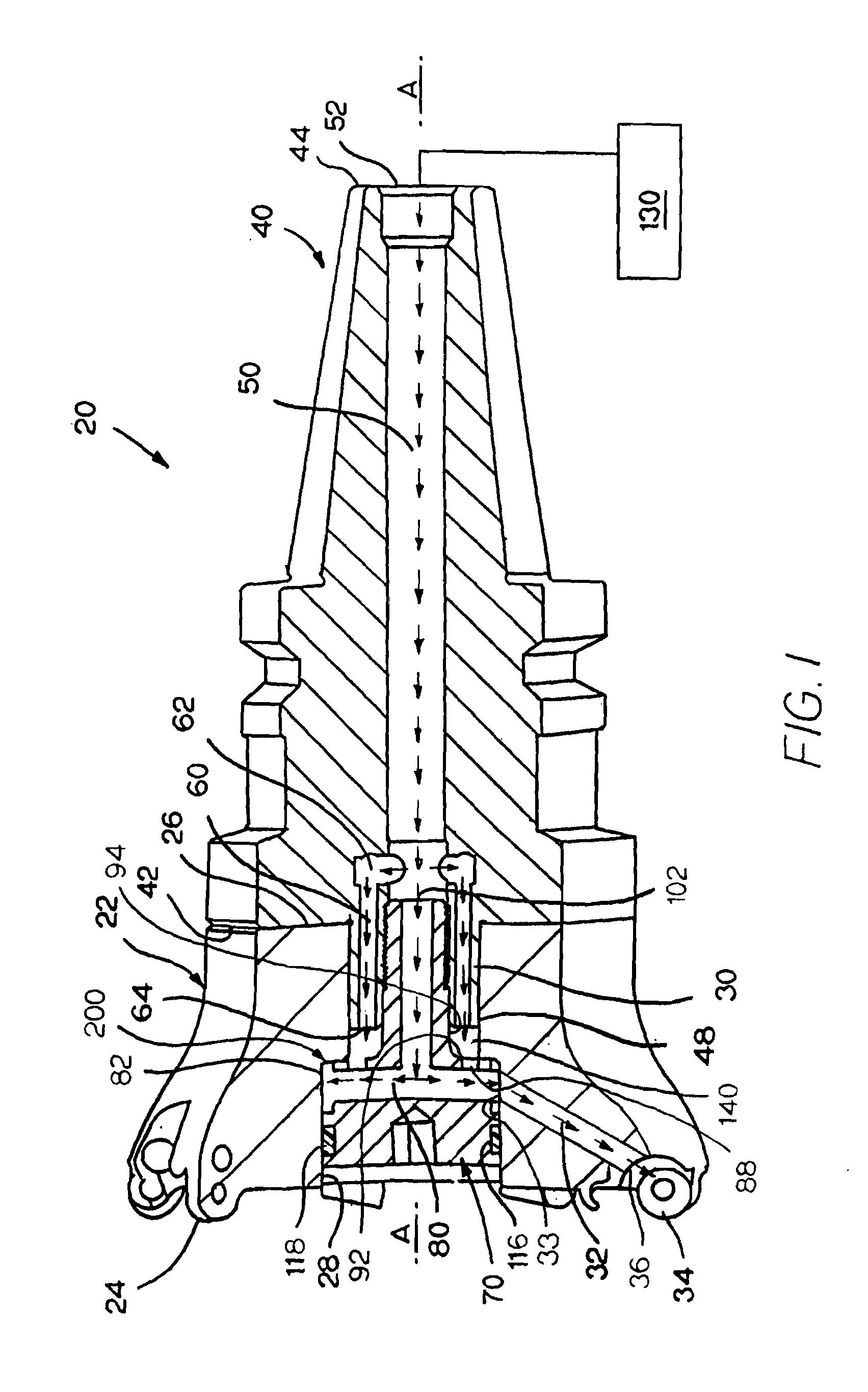
[0021]Referring to the drawings, FIG. 1 is a side view of one specific embodiment a cutting tool generally designated as 20. The cutting tool 20 comprises an assembly of the cutter body generally designated as 22, the adapter generally designated as 40 and the locking screw generally designated as 70. The cutter body 22 is at the axial forward end of the cutting tool 20 and the adapter 40 is at the axial rearward end of the cutting tool 20. The cutter body 22 has an axial forward end 24 and an axial rearward end 26. The cutter body 22 further contains a central aperture 28 and a pilot hole 30.

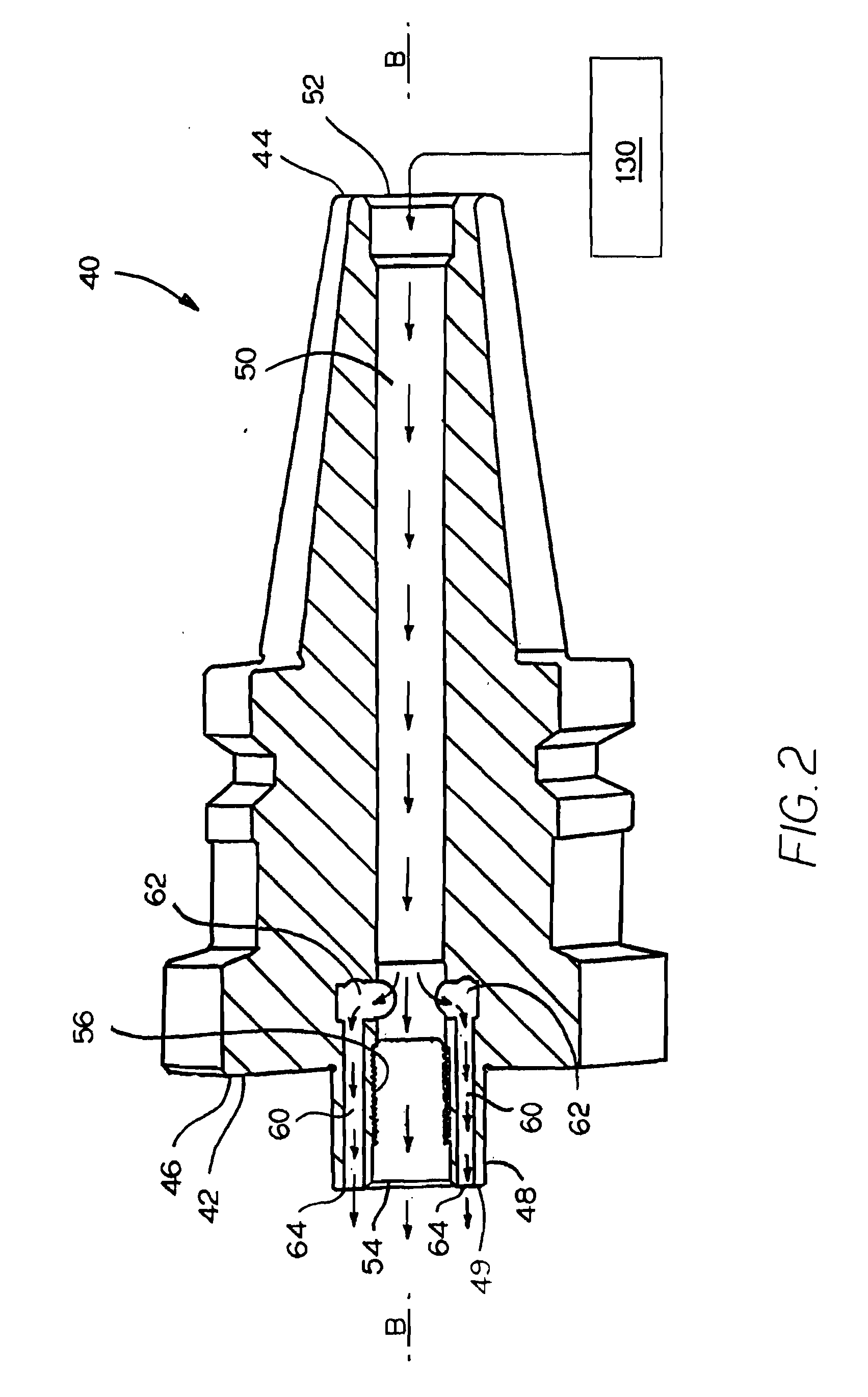
[0022]The cutter body further contains at least one cutter body coolant passage 32. Each one of the cutter body coolant passages 32 exits toward a cutting insert seat 34 wherein coolant discharges or sprays from a discharge opening 36 toward the cutting insert and / or the vicinity of the cutting insert-workpiece interface. Coolant enters the coolant passage 32 through an entrance 33. Typically, ...


PUM

PropertyMeasurementUnit
volumeaaaaaaaaaa
lengthaaaaaaaaaa
flexibilityaaaaaaaaaa

Abstract

A cutting tool has a cutter body, which carries a cutting insert, and an adapter, which has a longitudinal adapter axis, wherein a locking screw attaches the cutter body to the adapter. A coolant volume is defined in a vicinity of a meeting of the cutter body, the adapter and the locking screw. The adapter contains an axial adapter bore. The locking screw contains a transverse locking screw bore in fluid communication with the axial adapter bore. The locking screw further contains a peripheral transverse locking screw bore passage in fluid communication with the coolant volume and the transverse locking screw bore. The coolant volume and the transverse locking screw bore are in fluid communication with the cutter body coolant passage.

Description

BACKGROUND OF THE INVENTION[0001]The present invention relates to machine tools, and more particularly, to a cutting tool that includes a cutter body along with a locking screw and an adapter. More specifically, the invention relates to the locking screw alone, as well as the combination of the locking screw with other components(s), that provide improved coolant delivery to the cutter body. Further, the invention relates to an improved locking screw, as well as the combination of the locking screw with other components(s), that provide an improvement to the design flexibility of the cutter body.[0002]In a conventional cutting arrangement, a cutter body retains or holds one or more cutting inserts. The cutter body operatively attaches to a machine such as, for example, a milling machine. An adapter is useful for the attachment of the cutter body to the milling machine wherein the locking screw secures the cutter body to the adapter. Typically, the milling machine drives the cutter b...

Claims


Application Information

Patent Timeline
Patent Type & Authority Applications(United States)
IPC IPC(8): B23C5/28
CPCB23Q11/1023B23C5/28B23C2210/02Y10T82/16065B23C2240/245Y10T407/14
Inventor HOFFER, BRAD D.FROTA DE SOUZA FILHO, RUYLONG, II, THOMAS J.GAMBLE, KEVIN M.WAGGLE, JAMES M.
Owner KENNAMETAL INC
Why Eureka
Try Eureka