

Rectal manipulation devices
- Summary
- Abstract
- Description
- Claims
- Application Information
AI Technical Summary
Problems solved by technology
Method used
Image

Examples
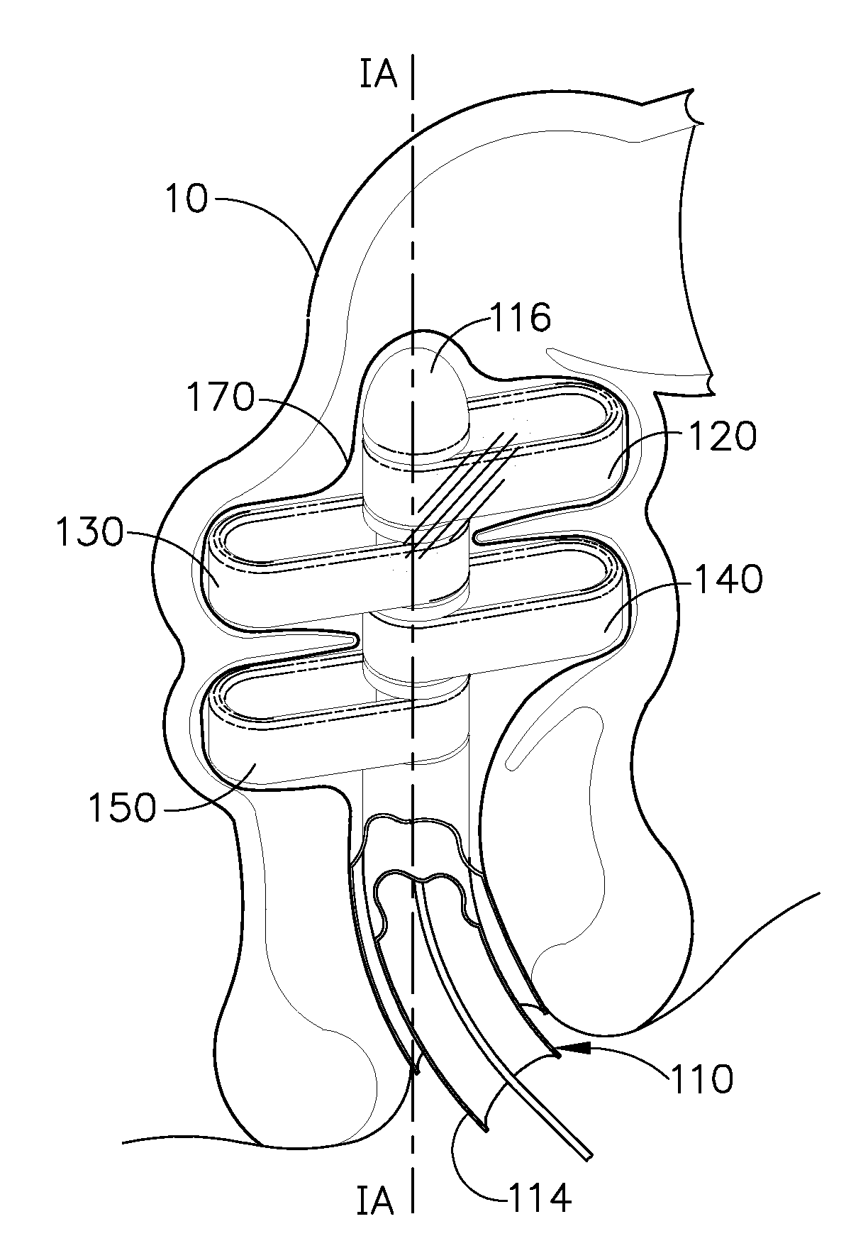
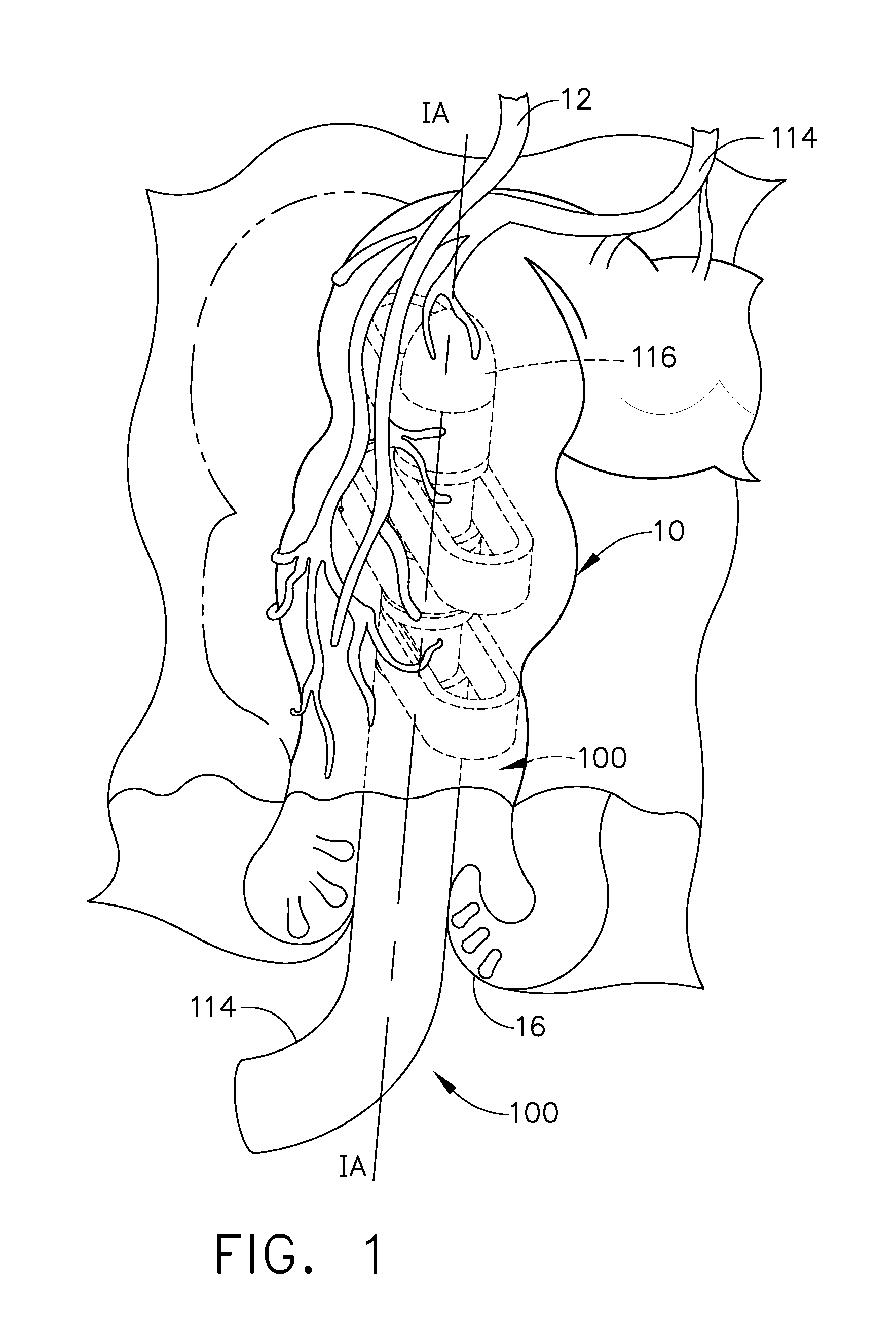
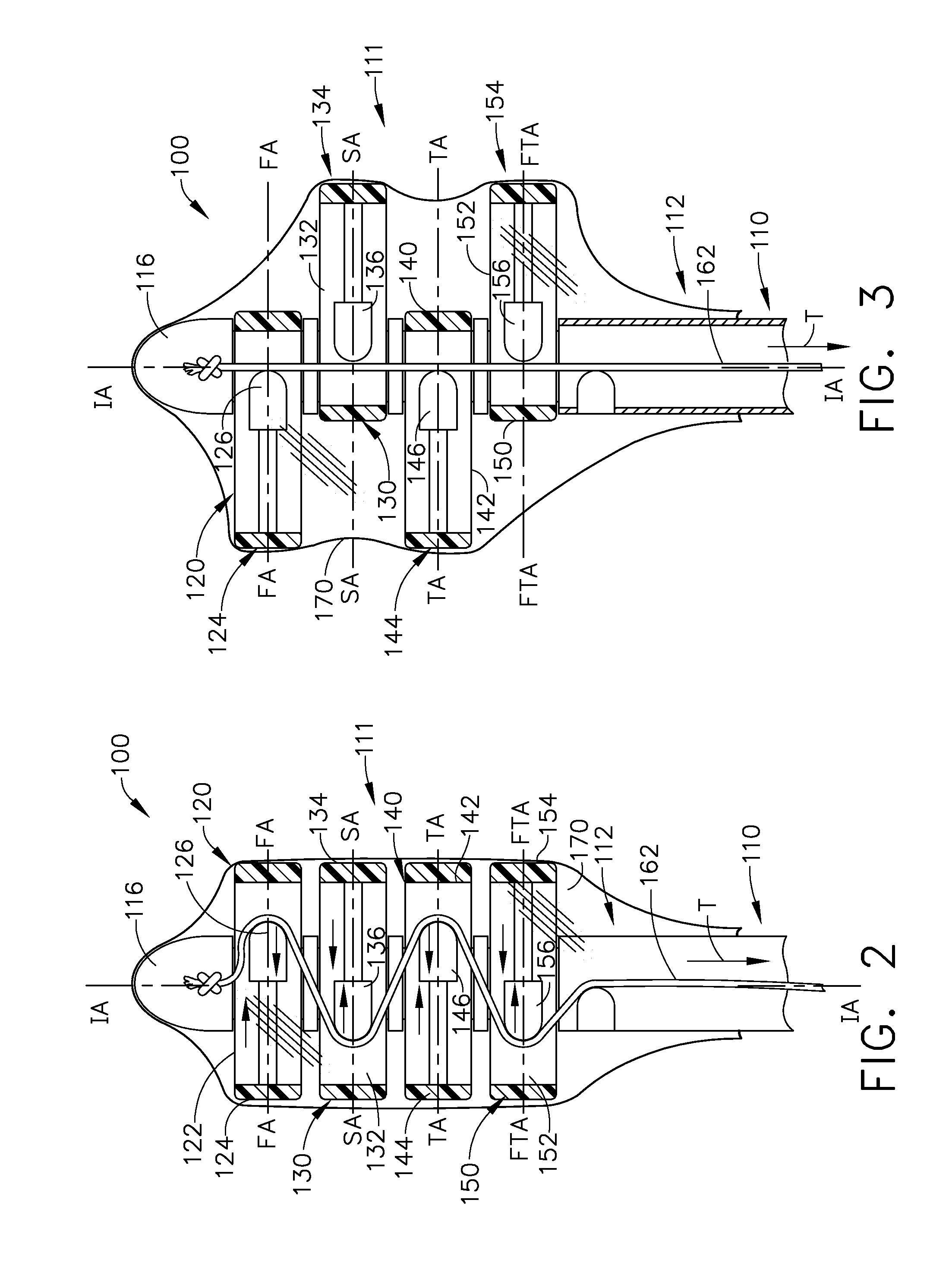
embodiment 100
[0054]FIGS. 5 and 6 illustrate an alternative tissue manipulation device embodiment 100′ that operates in substantially the same manner as the tissue manipulation device described above. However, in this embodiment, when the tissue manipulation arms 120, 130, 140, 150 are in the initial insertion position or orientation, all of the all of the ends 124, 134, 144, 154 of the tissue manipulation arms 120, 130, 140, 150, respectively are substantially aligned along one side of the insertion axis IA-IA. Then, when an actuation motion “T” is applied to the cable 162, only the second tissue manipulation arm 130 and the fourth tissue manipulation arm 150 move laterally along their respective axes SA-SA and FTA-FTA. Thus, in this embodiment, the first tissue manipulation arm 120 and the third tissue manipulation arm 130 do not move laterally upon application of a tension force “T” to the cable 162. However, each of the tissue manipulation arms 120, 130, 140, 150 may be spring biased to enabl...
embodiment 200
[0055]FIGS. 7-10 illustrate another tissue manipulation device embodiment 200. In various embodiments, the tissue manipulation device 200 includes a central shaft assembly 210 that has an outer shaft 212 that has a substantially straight distal end portion 213 that defines an insertion axis IA-IA. The central shaft assembly 210 may further have a proximal portion (not shown) that is curved to facilitate ease of control and insertion of the distal end portion 212 and the head assembly generally designated as 211 into the colon 10 through the anus 16 in the manner described above.
[0056]In at least one form, the tissue manipulation device 200 further comprises a plurality of tissue manipulation arms 220, 230, 240, 250 that are operably supported on the central shaft assembly 210. More specifically, a first tissue manipulation arm 220 comprises a first body portion 222 that has a relatively blunt first tissue manipulation end 224. The body portion 222 of the first tissue manipulation ar...
embodiment 300
[0062]FIGS. 11-14 illustrate another tissue manipulation device embodiment 300. In various embodiments, the tissue manipulation device 300 includes a central shaft assembly 310 that has an outer shaft assembly 312 that defines an insertion axis IA-IA. The outer shaft assembly 312 includes a distal portion 314 that is separated from a central portion 216 by a slot or gap 315, and a proximal portion 318 that is separated from the central portion 316 by a slot or gap 317. The proximal portion 318 may be curved near to its proximal end to facilitate ease of control and insertion of the head assembly generally designated as 311 into the colon 10 through the anus 16 in the manner described above.
[0063]In at least one form, the tissue manipulation device 300 further comprises a plurality of tissue manipulation arms 320, 330, 340, 350 that are operably supported on the central shaft assembly 310. More specifically, a first tissue manipulation arm 320 comprises a first body portion 322 that ...
PUM
 Abstract
Description
Claims
Application Information