Creating graphical models representing control flow of a program manipulating data resources

a technology of manipulating data resources and graphical modeling, applied in the field of software development, can solve problems such as not direct, obvious use of uml representations in order, and general limitation to documenting behavior

Inactive Publication Date: 2012-09-20
IBM CORP
View PDF6 Cites 5 Cited by
  • Summary
  • Abstract
  • Description
  • Claims
  • Application Information

AI Technical Summary

Problems solved by technology

However, there is not a direct, obvious usage of UML representations in order to represent procedural artifacts, such as described in COBOL language.
Existing literature describes some techniques to use these UML diagrams for COBOL programs but they are generally limited to documenting behavior.

Method used


Image

  • Creating graphical models representing control flow of a program manipulating data resources
  • Creating graphical models representing control flow of a program manipulating data resources
  • Creating graphical models representing control flow of a program manipulating data resources

Examples


Embodiment Construction

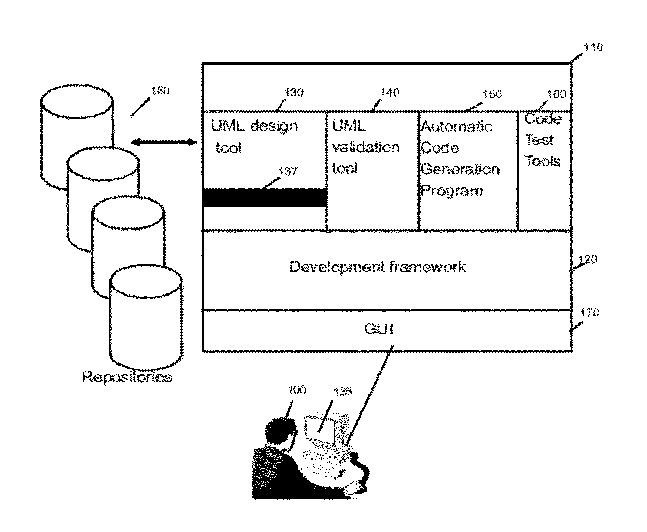
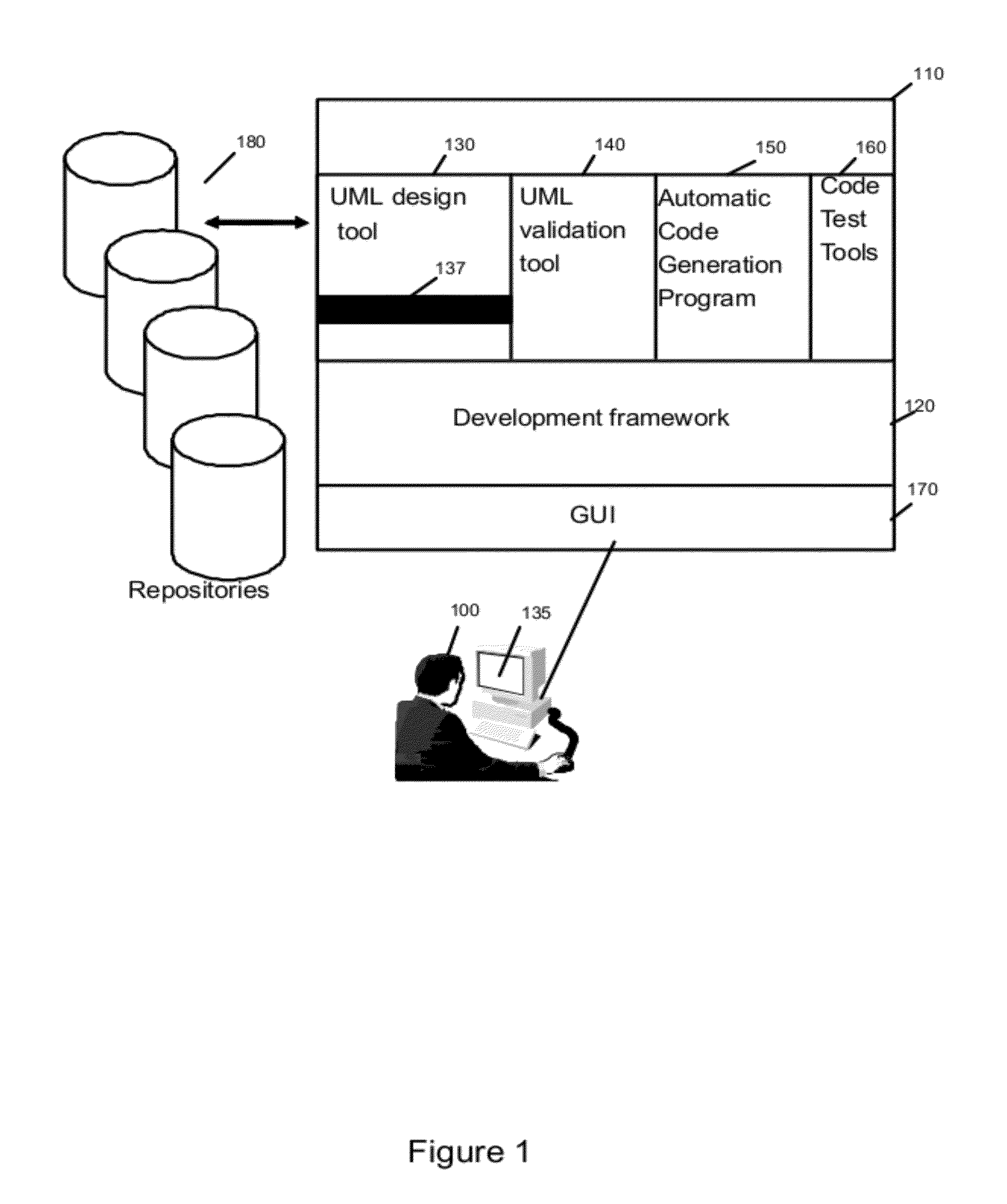
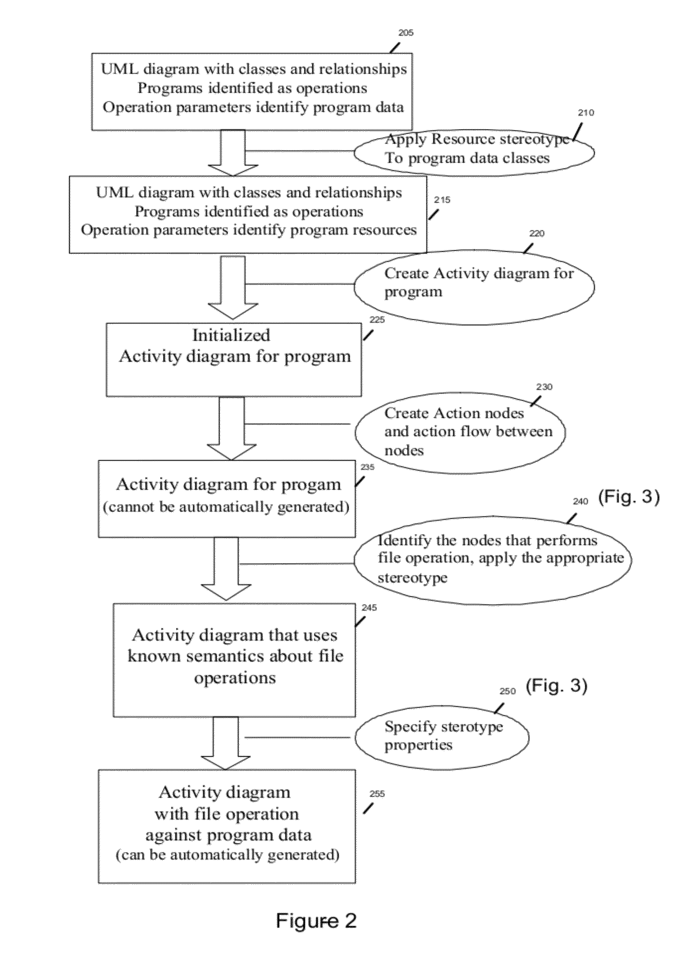
[0011]One aspect of the invention represents control flow information of a program which includes actions to manipulate data resources in a way allowing systematic code generation. Embodiments of the present invention include a method, system, and computer program product for creating a design model for programs in an application which represent the operations on resources performed by the program.

[0012]The new model can include a class diagram which is enhanced with two new stereotypes (in UML 2.0) for “Program” and “Resource” (a file, table, etc.). Each activity diagram corresponding to one program of the application is enriched with stereotypes for operations on the resources “open”, “write”, “read”, “delete”, “update”. Furthermore, a “call” stereotype can be created for “call” to subprogram operations. The new model will be used for a complete view of the programs in the following steps of the development process. Furthermore, as a semantic is created the model can be automatica...


PUM


Abstract

A computing device can store a class diagram of an application in a storage medium. A new model element type is applied to class operations in the class diagram and to a resource new model element type to data classes by defining properties, which include at least a resource name property, for each new model element. Flow diagrams of the application are applied to as many new model element types as different types of actions exist in the flow diagrams. The actions represent the operations on resources.

Description

CROSS-REFERENCE TO RELATED APPLICATIONS[0001]This continuation application claims the benefit of U.S. patent application Ser. No. 12 / 397,564 filed 4 Mar. 2009, which claims the benefit of European Patent Application No. 08305064.1 filed 21 Mar. 2008, entitled “A METHOD AND SYSTEM TO CREATE GRAPHICAL MODELS REPRESENTING CONTROL FLOW OF A PROGRAM MANIPULATING DATA RESOURCES”, which is assigned to the assignee of the present application.BACKGROUND[0002]The present invention generally relates to software development and, more particularly, to representing a control flow of a program manipulating data resources using graphical modeling.[0003]Software applications can be modeled using standardized specification languages such as Unified Modeling Language (UML), which is a visual specification language. The models, such as the class diagrams, created with UML are then derived to actual programming code. UML is often used for Object Oriented development but is more commonly adopted by the i...

Claims


Application Information

Patent Timeline
Patent Type & Authority Applications(United States)
IPC IPC(8): G06F9/44
CPCG06F17/30864G06F2221/2103G06F21/36G06F16/951
Inventor DANGEVILLE, NICHOLASPONIN, JOHAN
Owner IBM CORP
Why Eureka
Try Eureka