Heat exchanger and associated method employing a stirling engine

a technology of stirling engine and heat exchanger, which is applied in the direction of indirect heat exchangers, machines/engines, lighting and heating apparatus, etc., can solve the problems of increasing the energy consumption of fans, and not generally very efficient convective heat transfer, so as to reduce or eliminate the energy cost and carbon footprint of heat exchangers.

Inactive Publication Date: 2012-09-27
THE BOEING CO
View PDF5 Cites 1 Cited by
  • Summary
  • Abstract
  • Description
  • Claims
  • Application Information

AI Technical Summary

Benefits of technology

[0006]A heat exchanger and associated method are provided according to embodiments of the present disclosure that may reduce or eliminate the energy costs and carbon footprint of a heat exchanger. In this regard, the heat exchanger and method of one embodiment may eliminate or reduce the need for an external mechanical or electrical power source to drive the fan. The heat exchanger and method of one embodiment may also eliminate any requirement that electrical wiring extend from an electrical power source to the fan.

Problems solved by technology

However, convective heat transfer is not generally very efficient.
While the movement of the secondary fluid across the coils of the heat exchanger increases the heat transfer rate, the increase in the heat transfer rate comes at the expense of the energy required to operate the fan.
In either instance, the fan increases the energy consumption of a heat exchanger.
As the fan is generally configured to be activated so long as heat transfer is required, the fan may consume energy over a fairly long period of time, thereby correspondingly increasing the operating costs and the carbon footprint of the heat exchanger.
In some applications, the routing, placement and handling of the electrical wiring may prove challenging, such as in instances in which the wiring must be routed over or along a hinge or other moveable joint.

Method used


Image

  • Heat exchanger and associated method employing a stirling engine
  • Heat exchanger and associated method employing a stirling engine
  • Heat exchanger and associated method employing a stirling engine

Examples


Embodiment Construction

[0024]Embodiments of the present disclosure now will be described more fully hereinafter with reference to the accompanying drawings, in which some, but not all embodiments are shown. Indeed, these embodiments may be embodied in many different forms and should not be construed as limited to the embodiments set forth herein; rather, these embodiments are provided so that this disclosure will satisfy applicable legal requirements. Like numbers refer to like elements throughout.

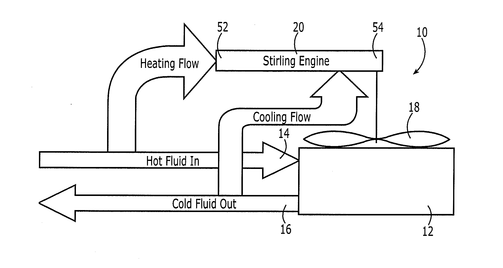
[0025]A heat exchanger 10 in accordance with one embodiment of the present disclosure is illustrated in FIG. 1. The heat exchanger 10 may include a plurality of coils 12 configured to carry a primary fluid. The primary fluid that is circulated through the plurality of coils 12 may be any of a variety of fluids including various gas or liquids. The plurality of coils 12 may include an inlet 14 through which the primary fluid enters and an outlet 16 through which the primary fluid exits. During the flow of the pri...


PUM


Abstract

A heat exchanger and associated method are provided that may eliminate or reduce the need for an external mechanical or electrical power source to drive the fan by utilization, instead, of a Stirling engine. A heat exchanger includes a plurality of coils configured to carry a primary fluid. The heat exchanger also includes a fan including a plurality of fan blades configured to force a secondary fluid across the plurality of coils to facilitate heat transfer between the primary and secondary fluids. The heat exchanger also includes a Stirling engine operably connected to the fan and configured to cause rotation of the fan blades. A corresponding method is also provided.

Description

TECHNOLOGICAL FIELD[0001]Embodiments of the present disclosure relate generally to heat exchangers and associated methods and, more particularly, to heat exchangers and associated methods that utilize a fan to increase the heat transfer rate.BACKGROUND[0002]It is desirable in many applications to provide for heat transfer, such as to either heat or cool a fluid or other workpiece. For example, a heat exchanger may remove waste heat from a mechanical or electrical system, such as an air conditioning condenser. One form of heat transfer is convective heat transfer. However, convective heat transfer is not generally very efficient. Indeed, to transfer heat, particularly a relatively large amount of heat, from one fluid to another, utilizing convective heat transfer, a relatively large heat transfer surface must generally be provided. To provide an expansive heat transfer surface, heat exchangers have been developed that include a plurality of coils configured to carry a primary fluid. ...

Claims


Application Information

Patent Timeline
Patent Type & Authority Applications(United States)
IPC IPC(8): F02G1/043F28F13/12
CPCF02G1/043F28D1/024F28F2250/08F02G2280/50
Inventor KWOK, DAVID W.MAULDIN, JACK W.
Owner THE BOEING CO
Why Eureka
Try Eureka