projector
- Summary
- Abstract
- Description
- Claims
- Application Information
AI Technical Summary
Benefits of technology
Problems solved by technology
Method used
Image
Examples
first modified example
2. Projector Related to a First Modified Example
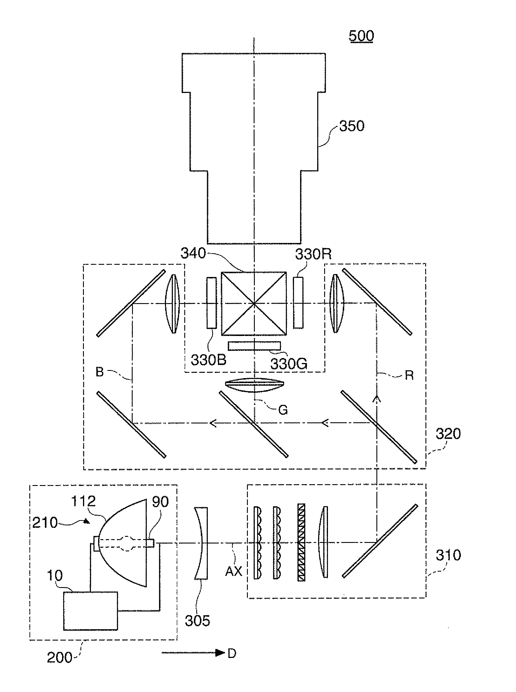
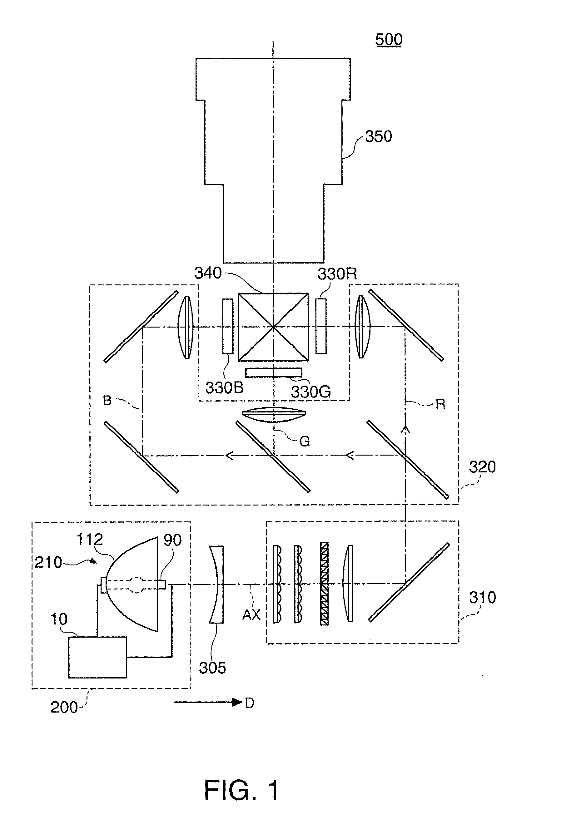
[0184]Next, a projector related to the first modified example will be described. The configuration such as an optical system and circuits of the projector related to the first modified example is the same as that of the above-described projector 500. Accordingly, a detailed example of the driving current I in the first modified example will be described hereinafter.
[0185]In the first modified example, it is exemplified that the third mode repeats a period in which the frequency of the driving current I is relatively high and a period in which the frequency of the driving current I is relatively low. Further, the principle to be described hereinafter may be applied in the same manner even in the case where the second mode repeats a period in which the frequency of the driving current I is relatively high and a period in which the frequency of the driving current I is relatively low.
[0186]Further, the transition period T13 is exemplified...
second modified example
3. Projector Related to a Second Modified Example
[0195]Next, a projector related to the second modified example will be described. The configuration such as an optical system and circuits of the projector related to the second modified example is the same as that of the above-described projector 500. Accordingly, a detailed example of the driving current I in the second modified example will be described hereinafter.
[0196]Further, the transition period T31 is exemplified hereinafter. Further, the principle to be described hereinafter maybe applied in the same manner even in the case of the transition period T21.
[0197]In the case where the operating mode after the transition period is a mode that repeats the first period in which the driving power is relatively low and the second period in which the driving power is relatively high, the control unit 40 may control the discharge lamp driving unit 230 so that the ratio of time when the frequency of the driving current I in the second p...
third modified example
4. Projector Related to a Third Modified Example
[0202]Next, a projector related to the third modified example will be described. The configuration such as an optical system and circuits of the projector related to the third modified example is the same as that of the above-described projector 500. Accordingly, a detailed example of the driving current I in the third modified example will be described hereinafter.
[0203]The control unit 40 may control the discharge lamp driving unit 230 so that the length of the transition period becomes longer as the time when the operating mode just before the transition period continues becomes longer.
[0204]FIG. 21 is a graph illustrating a control example in a transition period T12, a transition period T13, and a transition period T23 in a third modified example. The horizontal axis represents the duration time of the operating mode just before the transition period, and the vertical axis represents the length of the transition period.
[0205]In an ...
PUM
 Abstract
Description
Claims
Application Information
 - Generate Ideas
- Intellectual Property
- Life Sciences
- Materials
- Tech Scout
- Unparalleled Data Quality
- Higher Quality Content
- 60% Fewer Hallucinations
Browse by: Latest US Patents, China's latest patents, Technical Efficacy Thesaurus, Application Domain, Technology Topic, Popular Technical Reports.
© 2025 PatSnap. All rights reserved.Legal|Privacy policy|Modern Slavery Act Transparency Statement|Sitemap|About US| Contact US: help@patsnap.com


