
Display device and method for driving same

a technology of display device and driving device, which is applied in the direction of instruments, electrical devices, pictoral communication, etc., can solve the problems of flicker and lateral shadow, and achieve the effect of enhancing display quality

Active Publication Date: 2021-01-12
TRIVALE TECH
View PDF42 Cites 0 Cited by
  • Summary
  • Abstract
  • Description
  • Claims
  • Application Information

AI Technical Summary

Benefits of technology

[0008]The present invention provides a technique capable of enhancing display quality in a display device capable of displaying a first image and a second image in parallel using a light deflecting member such as a parallax barrier system, and capable of performing two-dimensional display by setting a parallax barrier in a full transmission state.
[0010]Since the polarities of the picture elements of each color are equally dispersed, occurrence of a flicker can be suppressed.

Problems solved by technology

However, in the techniques of Japanese Patent Nos. 2857429, 3096613, and 6057647, there is a problem that a so-called flicker occurs when the first image and the second image formed by using the pixel for the right eye and the pixel for the left eye are displayed by the liquid crystal display panel.
In addition, as described in PCT International Publication No. 2011 / 078168, there is a problem that a phenomenon called lateral shadow may occur when a window pattern is displayed in a single color in the first image and the second image.

Method used


Image

  • Display device and method for driving same
  • Display device and method for driving same
  • Display device and method for driving same

Examples


first preferred embodiment

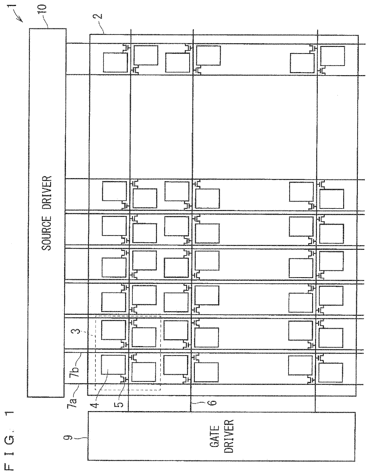
[0034]FIG. 1 is a diagram showing a configuration of a liquid crystal display device 1 according to a first preferred embodiment of the present invention. The liquid crystal display device 1 in FIG. 1 includes a transmissive liquid crystal panel 2, a gate driver 9, and a source driver 10. The liquid crystal panel 2 is a display panel, and the gate driver 9 and the source driver 10 are drivers.

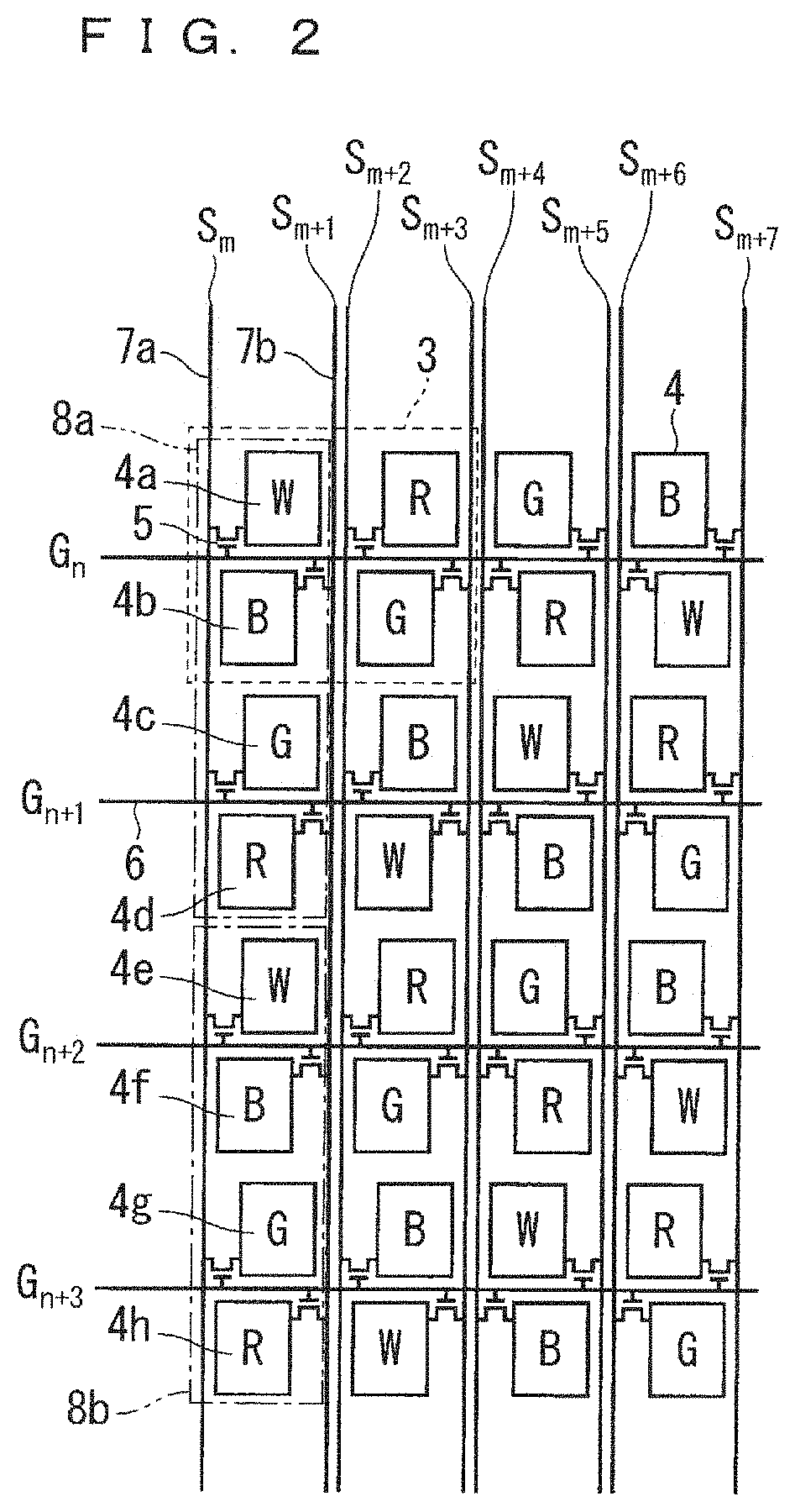
[0035]The liquid crystal panel 2 includes, as one pixel (pixel) 3, a total of four picture elements (sub-pixels) 4 arranged in two rows in a vertical direction and two columns in a horizontal direction. A color of the picture element 4 is determined by a color of a color filter provided in each picture element region. Note that an arrangement of the color filters, that is, an arrangement of colors of the picture elements 4 will be described later with reference to FIG. 2 and the like.

[0036]The liquid crystal panel 2 is provided with a plurality of the picture elements 4 arranged in a matrix for...

second preferred embodiment

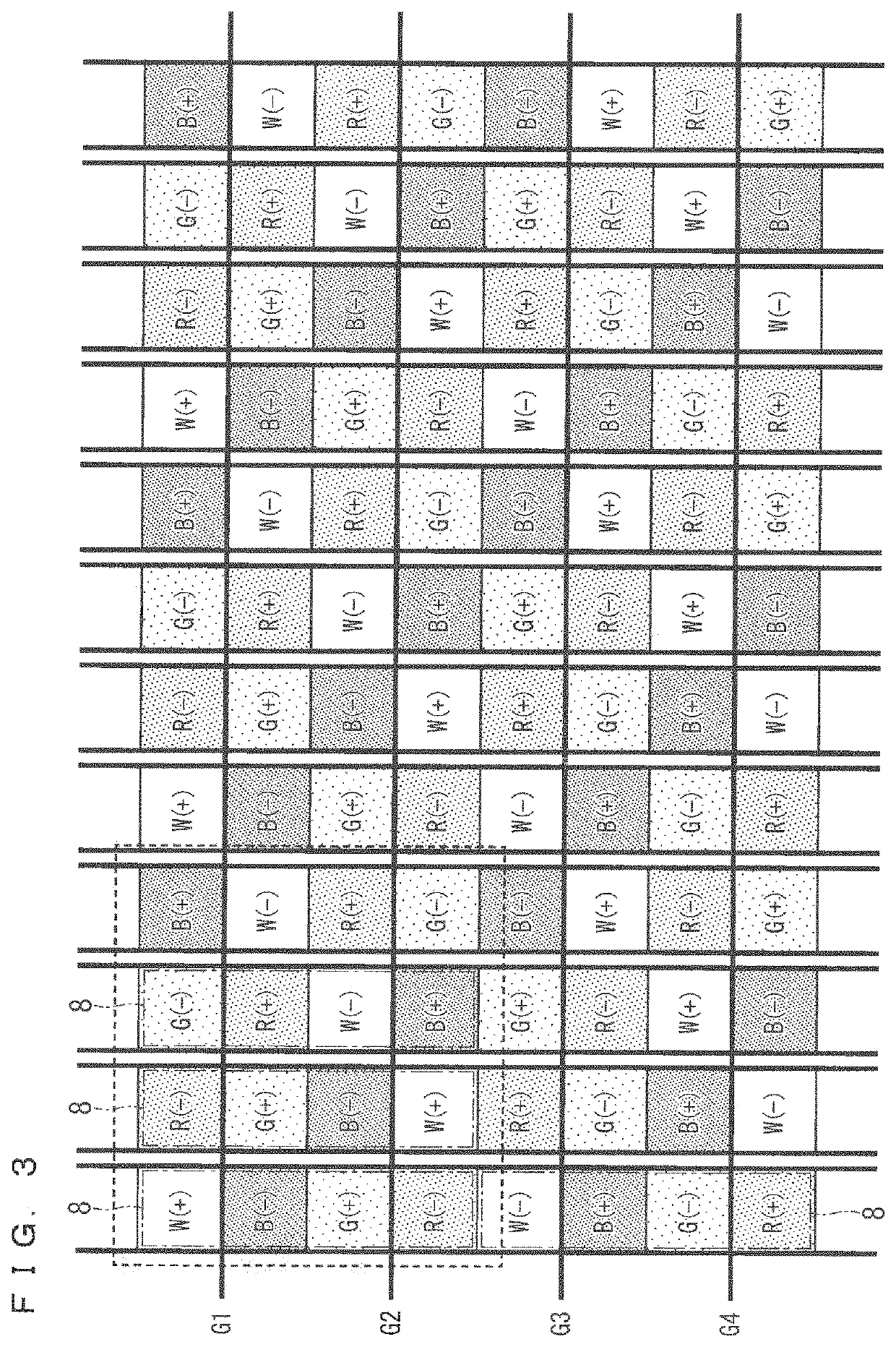
[0071]FIGS. 7, 8, and 9 are diagrams each showing a polarity arrangement in a certain frame of a liquid crystal panel 2 according to a second preferred embodiment of the present invention, similarly to FIGS. 3, 4, and 5. FIG. 7 shows picture elements 4 for 8 picture element rows×12 picture element columns obtained by repeating picture elements 4 of 4 picture element rows×4 picture element columns surrounded by a broken line square. The arrangement of picture elements 4 in FIG. 7 is different from the arrangement of picture elements 4 in FIG. 3 described in the first preferred embodiment.

[0072]Specifically, in the arrangement in FIG. 3, the green and white picture elements 4 are each arranged in the tilt direction which is the direction from the lower left to the upper right, and the red and blue picture elements 4 are each arranged in the tilt direction which is the direction from the lower right to the upper left. On the other hand, in the arrangement in FIG. 7, green and white pic...

third preferred embodiment

[0074]Prior to describing a liquid crystal display device 1 according to a third preferred embodiment of the present invention, a display of the liquid crystal display device 1 according to the first preferred embodiment will be described with reference to FIGS. 10, 11 and 12 corresponding to FIGS. 3, 4 and 5. In the following description, among two picture elements 4 in two vertical rows constituting one pixel 3, a picture element 4 provided on an upper side of a gate wiring line 6 in a plan view is sometimes referred to as “upper picture element 4”, and a picture element 4 provided on a lower side of the gate wiring line 6 in the plan view is sometimes referred to as “lower picture element 4”.

[0075]As in the first preferred embodiment, in the configuration in which one pixel 3 is formed by 4 picture elements 4 in 2 vertical rows×2 horizontal columns and the gate wiring line 6 is provided between the picture elements 4 in the 2 vertical rows, the lower picture element 4 of one gate...


PUM


Abstract

A display device includes drivers. The drivers apply a voltage having a polarity opposite to a polarity of a voltage applied to red, green, blue, and white picture elements in one first picture element columns to red, green, blue, and white picture elements in another first picture element columns adjacent to the one first picture element columns, and apply a voltage having a polarity opposite to a polarity of a voltage applied to red, green, blue, and white picture elements in one second picture element columns to red, green, blue, and white picture elements in another second picture element columns adjacent to the one second picture element columns.

Description

BACKGROUND OF INVENTIONField of the Invention[0001]The present invention particularly relates to a display device capable of displaying a first image and a second image in parallel using a light deflecting member, such as a parallax barrier system, and a method for driving the same.Description of the Background Art[0002]In recent years, as a display device capable of displaying a first image and a second image in parallel, an autostereoscopic image display device capable of visually recognizing a stereoscopic image without requiring special eyeglasses has been proposed.[0003]For example, Japanese Patent No. 2857429 discloses a three-dimensional display device including: barrier generating means for generating a parallax barrier stripe by electronically controlling a transmissive display element; a display screen disposed at a predetermined distance behind the barrier generating means and in which a stripe-shaped left eye image and a stripe-shaped right eye image are alternately arra...

Claims


Application Information

Patent Timeline
Patent Type & Authority Patents(United States)
IPC IPC(8): G09G3/36H04N13/359H04N13/324H04N13/31G09G3/00H04N13/356G02B30/27G02B30/30
CPCG09G3/3614G02B30/27G09G3/003H04N13/31H04N13/324H04N13/356H04N13/359G09G2320/0247G09G2340/0457G02B30/30
Inventor NOJIRI, ISAOMURAI, HIROYUKI
Owner TRIVALE TECH
Features
  • Generate Ideas
  • Intellectual Property
  • Life Sciences
  • Materials
  • Tech Scout
  • Unparalleled Data Quality
  • Higher Quality Content
  • 60% Fewer Hallucinations
Learn More