Image forming apparatus
a technology of image forming apparatus and forming apparatus, which is applied in the direction of electrographic process apparatus, instruments, optics, etc., can solve the problems and achieve the effect of reducing the productivity of an image forming apparatus
- Summary
- Abstract
- Description
- Claims
- Application Information
AI Technical Summary
Benefits of technology
Problems solved by technology
Method used
Image

Examples
embodiment 1
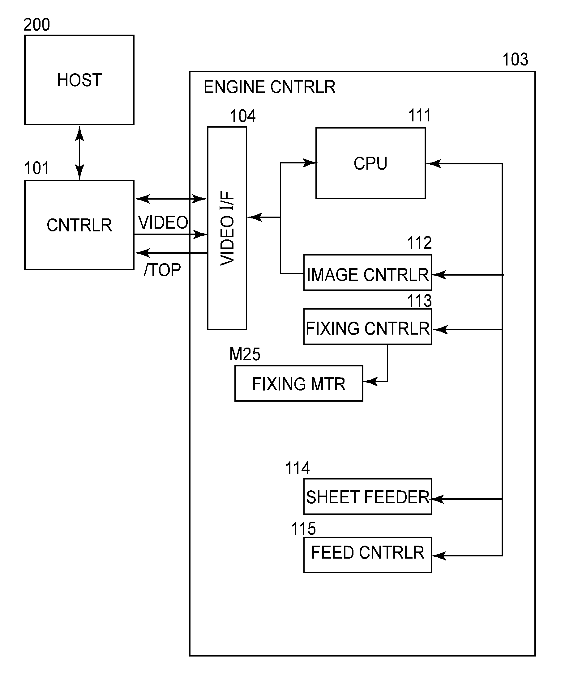
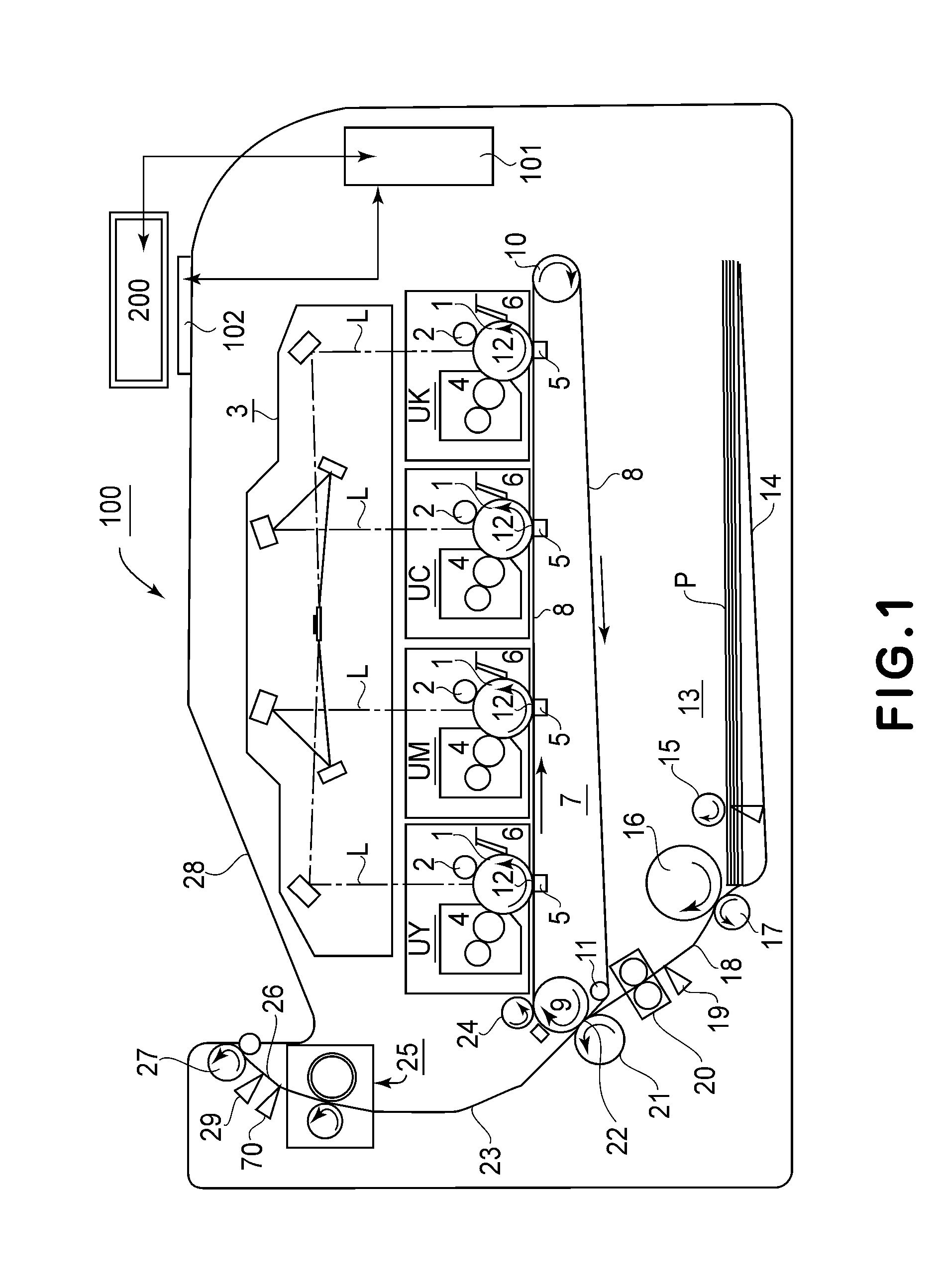
[0028](1) General Description of Image Forming Apparatus
[0029]FIG. 1 is a schematic sectional view of the image forming apparatus 100 in this embodiment, the fixing device 25 of which is an image heating apparatus in accordance with the present invention. It shows the general structure of the apparatus 100.
[0030]This image forming apparatus 100 is of the so-called inline (tandem) type, and also, of the so-called intermediary transfer type. More specifically, it is an electrophotographic full-color laser printer. It has multiple (four) image formation stations UY, UM, UC, and UK, each of which has an image bearing member 1. When it is in the full-color mode, it forms multiple (four) monochromatic toner images, different in color, with the use of its multiple (four) image formation stations, one for one, and synthetically forms a full color image by layering the four monochromatic toner images. It forms a full-color toner image on a sheet P of recording medium, based on the image data...
embodiment 2
[0135]The image forming apparatus 100 and fixing device 25 in this embodiment are the same in structure as those in the first embodiment. Therefore, they are not going to be described here. Next, referring to FIG. 13, their operation sequences, which are carried out after the detection of the “off-center sheet conveyance”, are described.
[0136]This embodiment is different from the first embodiment in that if the “off-center sheet conveyance” is detected, it is determined that a printing error has occurred. More specifically, when a sheet P of recording medium is being conveyed off-center, the sheet P is misaligned with an image to be formed thereon. Therefore, it is possible that the resultant image will be practically unusable.
[0137]In this embodiment, therefore, as the “off-center sheet conveyance” is detected, pressure is temporarily removed from the nip N, and then, pressure is applied again after a preset length of time. Then, the controller 101 determines that a printing error ...
embodiment 3
[0145]The image forming apparatus 100 and fixing device 25 in this embodiment are different from those in the first embodiment in that the substrate layer 41a of the film 41 of the fixing device 25 in this embodiment is made to be 70 μm in thickness, being thicker than that in the first embodiment, which is 55 μm in thickness. In other words, the film 41 in this embodiment is stronger than that in the first embodiment. Otherwise, the structural features of the image forming apparatus 100 and fixing device 25 in this embodiment are the same as those of the image forming apparatus 100 and fixing device 25 in the first embodiment, and therefore, are not going to be described here.
[0146]In this embodiment, as soon as the controller 101 detects that two (or more) sheets P of recording medium were consecutively conveyed off-center, it begins to count the sheets P of recording medium as they are conveyed through the fixing device 25. Then, as the counts exceeds a preset value, the controll...
PUM
 Abstract
Description
Claims
Application Information
 - R&D
- Intellectual Property
- Life Sciences
- Materials
- Tech Scout
- Unparalleled Data Quality
- Higher Quality Content
- 60% Fewer Hallucinations
Browse by: Latest US Patents, China's latest patents, Technical Efficacy Thesaurus, Application Domain, Technology Topic, Popular Technical Reports.
© 2025 PatSnap. All rights reserved.Legal|Privacy policy|Modern Slavery Act Transparency Statement|Sitemap|About US| Contact US: help@patsnap.com