
Door hinge for motor vehicles

a door hinge and motor vehicle technology, applied in the direction of door/window fittings, multi-purpose tools, construction, etc., can solve the problems of high cost, cumbersome housing manufacture, and overhead assembly, and achieve the effect of high detent torque, simple manner, and adjustability of spring for

Inactive Publication Date: 2012-10-04
METALSA AUTOMOTIVE
View PDF12 Cites 9 Cited by
  • Summary
  • Abstract
  • Description
  • Claims
  • Application Information

AI Technical Summary

Benefits of technology

[0005]Based on the above, it is the object of the present invention to provide a motor vehicle door hinge of the initially mentioned type that can be manufactured in a cost-effective manner.

Problems solved by technology

Motor vehicle door hinges with arresters serve to mount a vehicle door on a vehicle body and various configurations are known from the state of the art, A basic problem with mounting the vehicle door on the vehicle body—if there is no continuous arresting of the position of the vehicle door—is the provision of the highest possible number of detent positions by the arrester so that the door is secured against inadvertent pivoting with respect to the vehicle body in as many opening positions as possible,
The housing of the arrester has the drawback of a cup-shaped configuration, however, into which the detent body carrier can only be placed in the housing interior from one side, which results in additional assembly overhead due to accessibility being restricted to only one side.
Furthermore, the manufacture of the housing is very cumbersome and expensive because its configuration, having a housing bottom, is complex.

Method used


Image

  • Door hinge for motor vehicles
  • Door hinge for motor vehicles
  • Door hinge for motor vehicles

Examples


Embodiment Construction

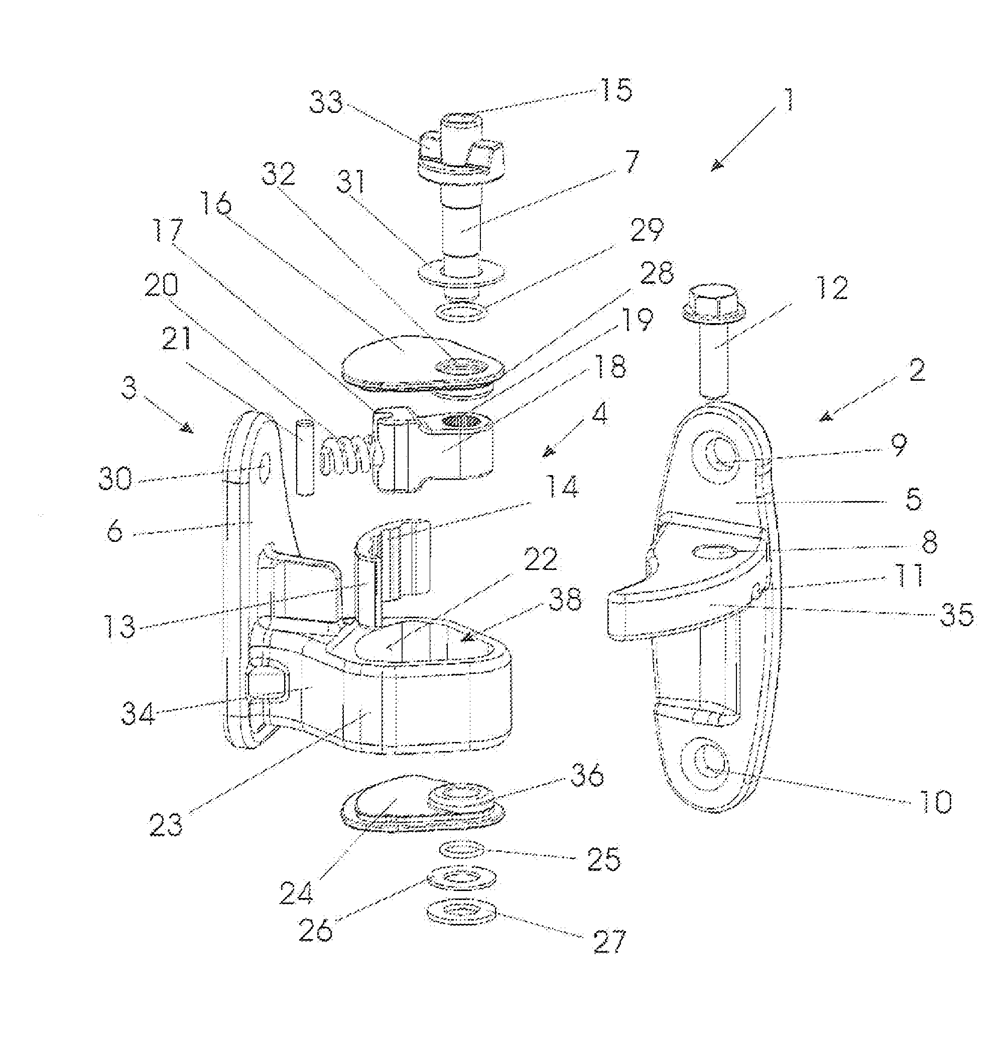
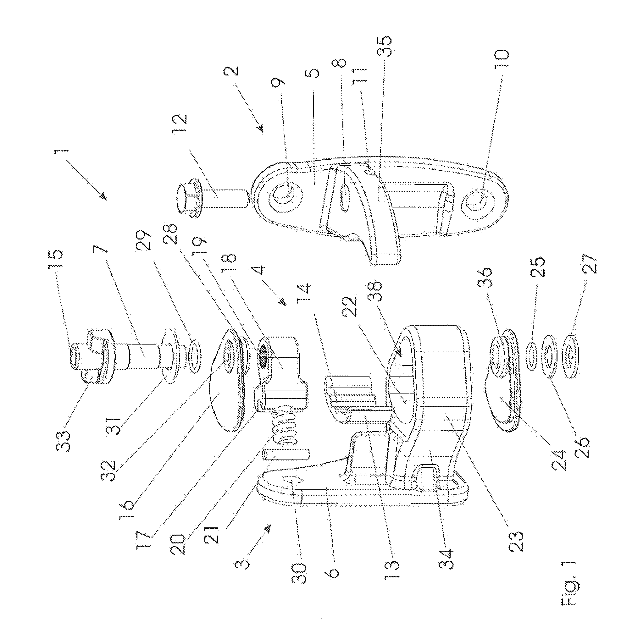
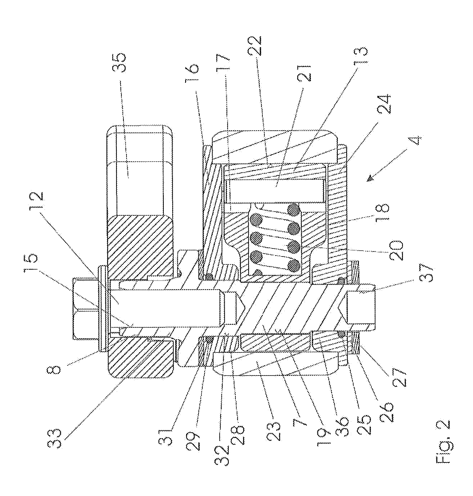
[0030]FIG. 1 shows a motor vehicle door hinge 1 with an arrester 4 in an exploded view, in which the individual parts of motor vehicle door hinge 1 are shown in a state separated from each other, wherein their relative arrangement with respect to a main axis is maintained.

[0031]Motor vehicle door hinge 1 has a pillar fitting 3 to be mounted on a vehicle body (not shown), and a door fitting 2 connected with pillar fitting 3 in a pivotable manner by means of a hinge pin 7, connectable to a motor vehicle door (also not shown) (cf. FIG. 2 to FIG. 4a).

[0032]Pillar fitting 3 has a base plate 6 for mounting on the vehicle body. It is provided with through holes 30 for receiving attachment screws by means of which pillar fitting 3 can be screwed to a vehicle body. Adjacent to base plate 6 of pillar fitting 3 is a beam 34 extending toward door fitting 2, on which a housing 23 of an arrester 4 is formed, explained in more detail below.

[0033]Beam 34 integrally formed with base plate 6 and thus...


PUM


Abstract

A motor vehicle door hinge, having a pillar fitting able to be mounted on a vehicle body, and a door fitting able to be mounted on a motor vehicle door, which are connected to each other in an articulated manner a hinge pin connected to either the pillar fitting or the door fitting in a rotation-resistant manner and to the remaining one of the pillar fitting or the door fitting in an articulated manner, and an arresting unit having a detent body carrier connected to the hinge pin in a rotation-resistant manner and radially extending to the latter and having a detent body, and a detent element adjustable on the other one of the pillar fitting or the door fitting with respect to the detent body carrier, coaxially arranged with respect to the hinge pin axis and in engagement with the detent body and including at least one detent notch, and arranged within a housing surrounding the hinge pin and the detent body carrier. To create a motor vehicle door hinge of the initially mentioned type that can be manufactured in a cost-effective manner, it is provided that the housing has a top and bottom housing opening opposing each other in the hinge axis direction and closed off by correspondingly formed closure elements, wherein both housing openings are formed in such a manner that they allow the hinge pin provided with the detent body carrier access to the housing interior.

Description

FIELD OF THE INVENTION[0001]The invention relates to a motor vehicle door hinge, comprising a pillar fitting able to be mounted on a vehicle body, and a door fitting able to be mounted on a motor vehicle door, which are connected to each other in an articulated manner by means of a hinge pin connected to either the pillar fitting or the door fitting in a rotation-resistant manner and to the remaining one of the pillar fitting or the door fitting in an articulated manner, and an arresting unit comprising a detent body carrier connected to the hinge pin in a rotation-resistant manner and radially extending to the latter and having a detent body, and a detent element adjustable on the other one of the pillar fitting or the door fitting with respect to the detent body carrier, coaxially arranged with respect to the hinge pin axis and in engagement with the detent body and including at least one detent notch, and arranged within a housing surrounding the hinge pin and the detent body car...

Claims


Application Information

Patent Timeline
Patent Type & Authority Applications(United States)
IPC IPC(8): E05D11/10E05D11/08
CPCE05Y2201/11E05Y2900/531E05D11/1071Y10T16/54028E05D11/1057Y10T16/53984Y10T16/54Y10T16/5403Y10T16/539
Inventor LOWEN, JAKOB
Owner METALSA AUTOMOTIVE
Learn More