Linear actuator

a linear actuator and actuator technology, applied in the field of electric motors, can solve the problems of high cost, limited method, and high cost of special lubricants that fit one particular application, and achieve the effect of high efficiency

Inactive Publication Date: 2013-10-24
JOHNSON ELECTRIC SA
View PDF21 Cites 17 Cited by
  • Summary
  • Abstract
  • Description
  • Claims
  • Application Information

AI Technical Summary

Benefits of technology

[0029]Preferably, the output shaft is restrained from rotating and is coupled to the rotor by a screw mechanism such that rotation of the rotor causes linear movement of the output shaft and the screw mechanism has a high efficiency.

Problems solved by technology

This method is critically limited for instance by temperature dependent effects like grease viscosity and material elasticities.
A special lubricant that fits one particular application works only in a limited parameter range and is expensive.
However, this significant increase in detent torque produces a high torque variation (torque ripple) resulting in a marked increase in the vibration and noise of the motor when it is operating, due to the superimposed detent torque creating a large fluctuation (ripple) in the resulting dynamic torque output. FIGS. 7 and 8 illustrate the effect of detent torque on the torque ripple of a stepper motor with a high detent torque which can be compared to the torque ripple of a typical stepper motor without detent torque as shown in FIG. 6.
By simply designing the motor section with an intentionally high magnetic detent torque leads to high vibration and audible noise during operation of the motor, which is undesirable.

Method used


Image

  • Linear actuator
  • Linear actuator
  • Linear actuator

Examples


Embodiment Construction

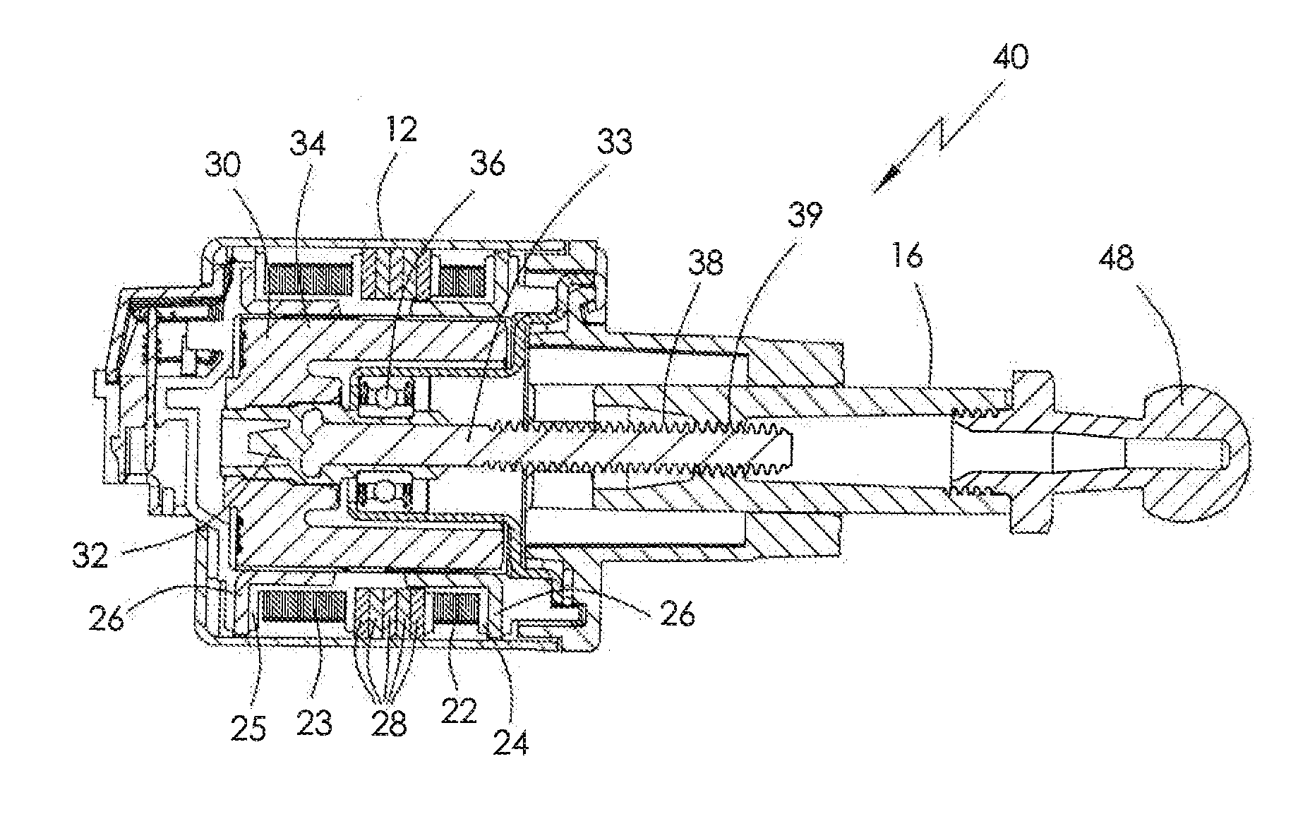
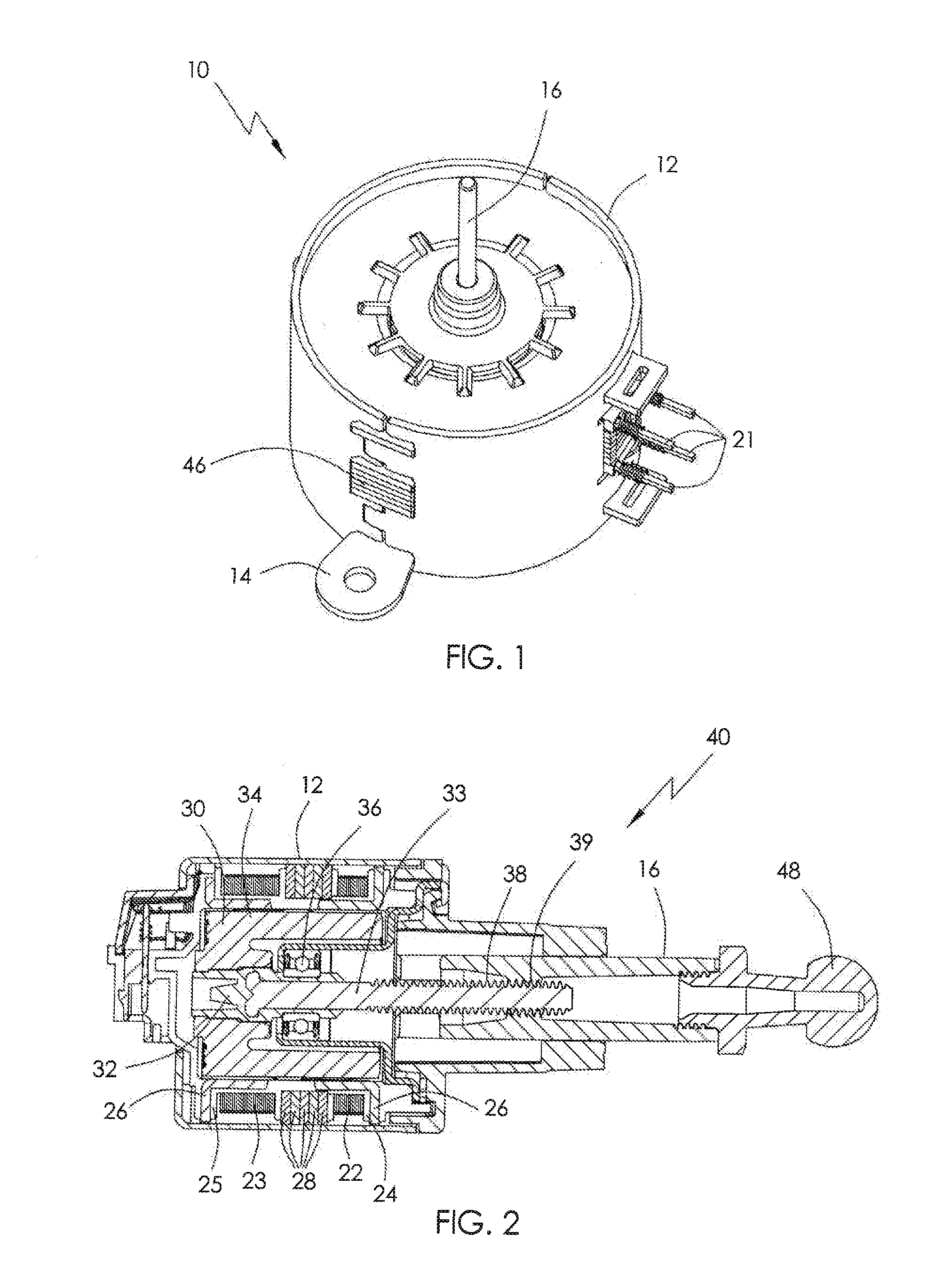
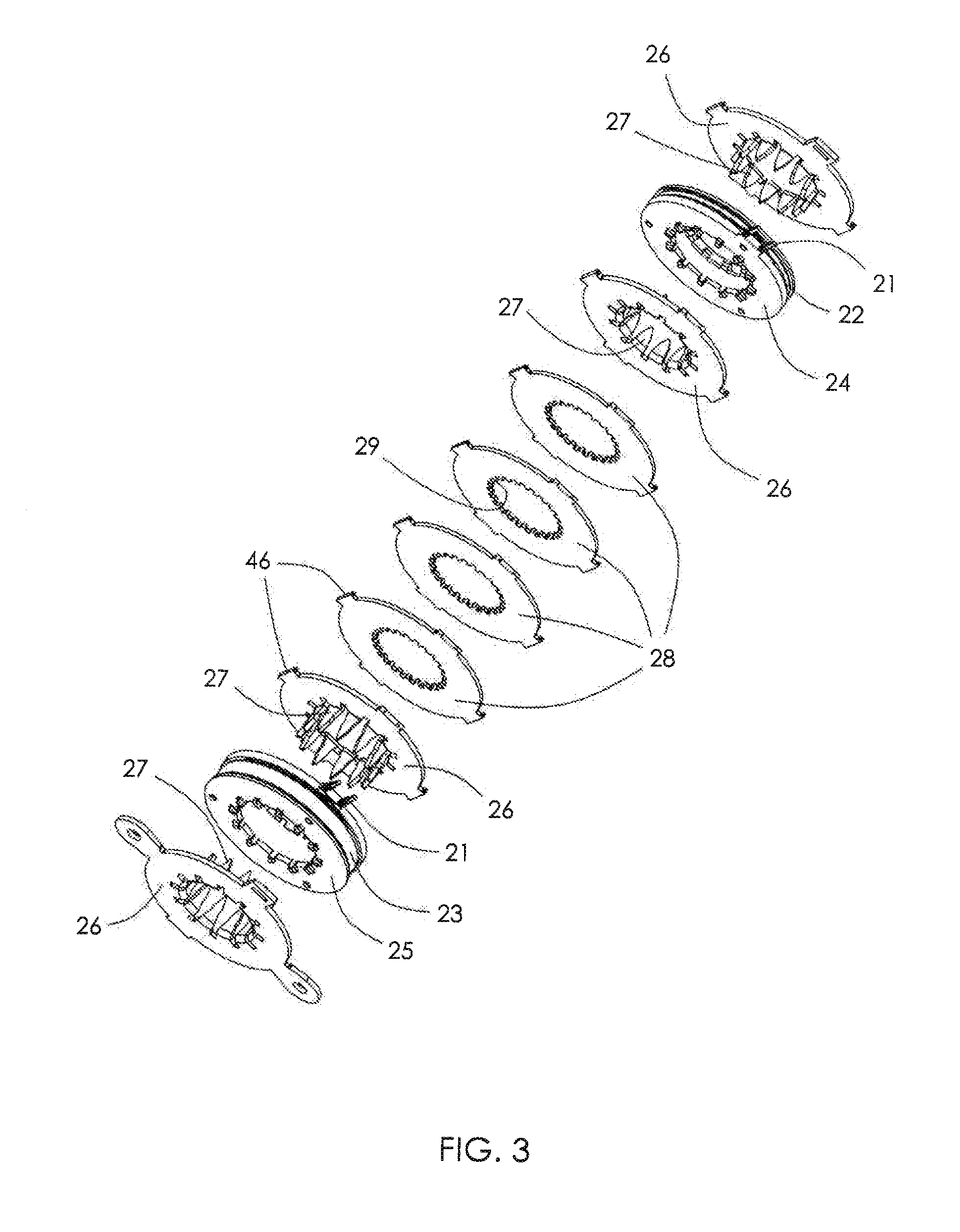
[0044]FIG. 1 illustrates a stepper motor 10 according to a preferred embodiment of the present invention. FIG. 2 is a longitudinal sectional view of a linear actuator according to a preferred embodiment of the present invention, and FIG. 3 is an exploded view of a part of the stator.

[0045]The stepper motor 10 of FIG. 1, has a housing 12 forming a part of the stator of the motor. The housing supports a number of stator plates, including a lower plate having mounting ears 14 with through holes for fixing the motor to an object. The motor has an output shaft 16 which in this case forms part of a rotor. The rotor is a permanent magnet rotor. The stator is a two phase wound stator and motor terminals 21 are seen extending from an opening in the housing. The construction of the stator will be described in detail with respect to FIG. 3.

[0046]The actuator 40 of FIG. 2 is of the linear type incorporating a stepper motor. The actuator is shown in section to illustrate the construction of one ...


PUM


Abstract

A linear actuator with a high holding force providing good irreversibility, has a high efficiency, low friction screw mechanism and a stepper motor with high magnetic detent torque but a low output torque ripple. The phase torque is modified to minimize the effect of the detent torque on the output. torque. Preferably, the motor has asymmetric phases to compensate for the detent torque.

Description

CROSS REFERENCE TO RELATED APPLICATIONS[0001]This non-provisional patent application claims priority under 35 U.S.C. §119(a) from Patent Application No. 201210121441.8 filed in The People's Republic of China on Apr. 23, 2012.FIELD OF THE INVENTION[0002]This invention relates to an electric motor and has particular application to a linear actuator incorporating a stepper motor having improved holding torque and low vibration.BACKGROUND OF THE INVENTION[0003]In certain automotive applications, such as head lamp adjusters, linear actuators are used for the dynamic regulation of devices. Linear displacement is provided by a threaded connection between the rotor core of a stepper motor and the output shaft. The output shaft is prevented from rotating thus rotation of the rotor causes the output shaft to move axially. The overall behavior of the actuator is strongly governed by the effects of friction.[0004]The stepper motor is designed for smooth operation to reduce vibration and audible...

Claims


Application Information

Patent Timeline
Patent Type & Authority Applications(United States)
IPC IPC(8): H02K37/14H02K7/06
CPCH02K37/14H02K7/06H02K7/106
Inventor BOURQUI, YVANFURLAN, MIHA
Owner JOHNSON ELECTRIC SA
Why Eureka
Try Eureka