Method and apparatus for aligning a wind turbine generator

a technology of wind turbine generator and wind turbine blade, which is applied in the direction of manufacturing tools, instruments, and gearing, etc., can solve the problems of premature and costly system failure, increase in weight, and increase in the need to ensure alignmen

Active Publication Date: 2012-10-04
DISCOVERY SOLAR ENERGY LLC
View PDF10 Cites 13 Cited by
  • Summary
  • Abstract
  • Description
  • Claims
  • Application Information

AI Technical Summary

Problems solved by technology

Since recent wind turbine generators tend to increase their output by increasing the size thereof, the sizes of components such as the rotor head, the main shaft, the gearbox, and the generator also increase, resulting in an increase in weight, and an increase in the need to assure alignment between the gearbox shaft and the generator main shaft.
Misalignment can lead to premature and costly failures of the system, as well as loss in income due to the inability to generate energy.
Accordingly, as market pressures continue to demand wind turbine systems that provide lower cost, greater reliability, and longer service lives, challenges remain and a need persists for improvements in methods and apparatuses for use in the maintenance of wind turbine systems.

Method used


Image

  • Method and apparatus for aligning a wind turbine generator
  • Method and apparatus for aligning a wind turbine generator
  • Method and apparatus for aligning a wind turbine generator

Examples


Embodiment Construction

[0019]Reference will now be made in detail to one or more examples of the invention depicted in the figures. Each example is provided by way of explanation of the invention, and not meant as a limitation of the invention. For example, features illustrated or described as part of one embodiment may be used with another embodiment to yield still a different embodiment. Other modifications and variations to the described embodiments are also contemplated within the scope and spirit of the invention.

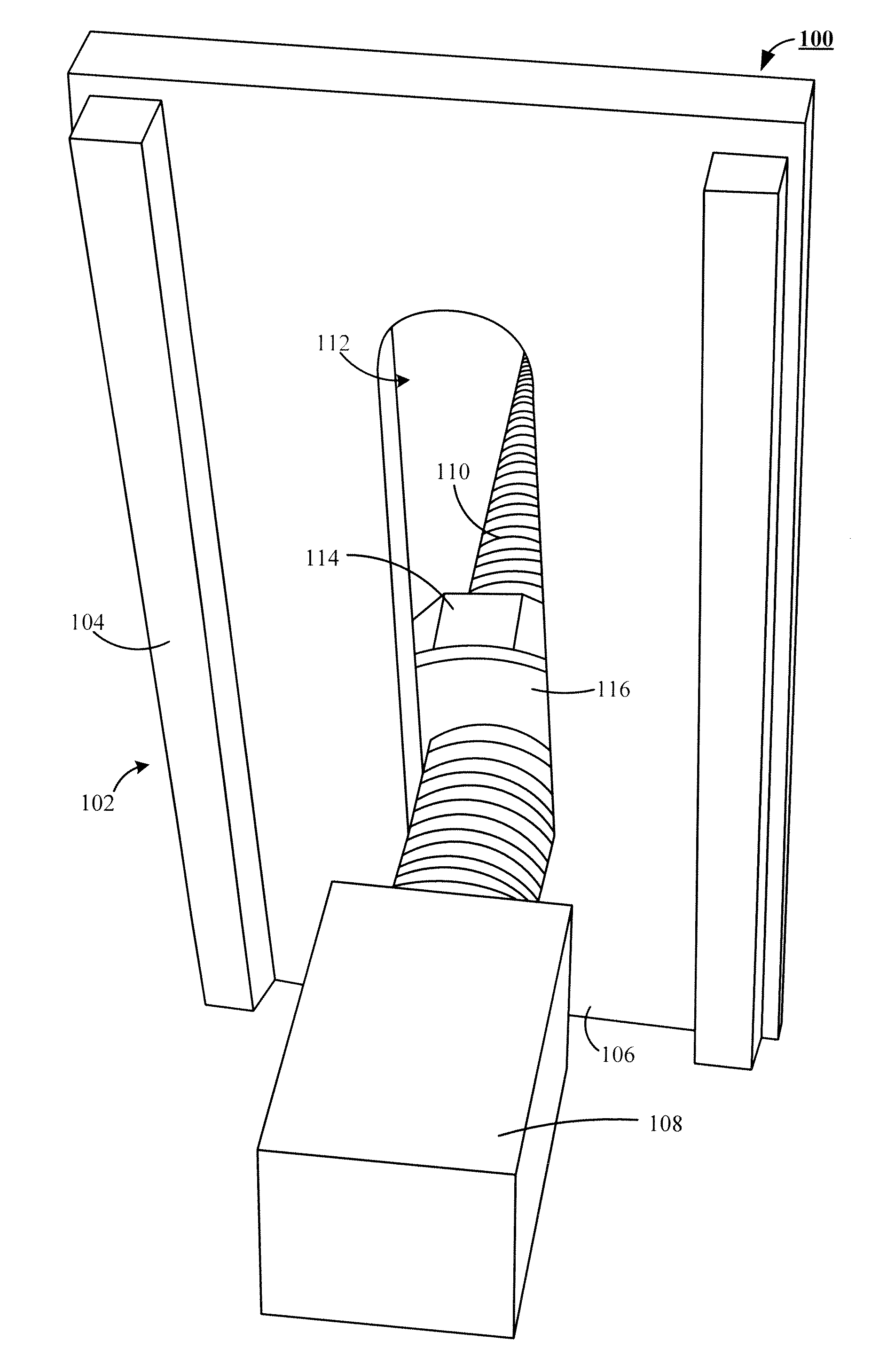
[0020]Referring to the drawings, FIG. 1 shows a preferred embodiment of an inventive wind turbine generator alignment tool 100 that includes a push plate 102 formed by a pair of push rails 104 secured to a force displacement plate 106, an end effector 108 interacting with a link member 110, which passes through an engagement aperture 112 of the force displacement plate 106. The preferred embodiment of the wind turbine generator alignment tool 100, when the end effector 108 is secured in its ...


PUM


Abstract

A method and apparatus for aligning an input shaft of a wind turbine generator with an output shaft of a wind turbine are disclosed. Preferably, the method includes placing a push plate of a wind turbine alignment tool into pressing contact with a selected support flange of a wind turbine generator identified by a misalignment measurement device. With the push plate positioned, an indexing means of the wind turbine alignment tool is advanced along an adjustment link member of the wind turbine alignment tool to impart an alignment force onto the selected support flange to align the input shaft of the wind turbine generator with the output shaft of the wind turbine. The method preferably concludes by rechecking the alignment of the input shaft of the wind turbine generator with the output shaft of the wind turbine.

Description

CROSS REFERENCE TO RELATED APPLICATION[0001]This application is a continuation of copending U.S. patent application Ser. No. 12 / 566,422 filed Sep. 9, 2009 which claims the benefit of priority to and is a patent application of U.S. Provisional Patent Application Ser. No. 61 / 095,520, entitled “Method For Aligning A Wind Turbine Generator.” filed Sep. 9, 2008. The aforementioned provisional patent application has not been assigned and the ownership resides solely with the inventor, and the entirety of the aforementioned patent application is incorporated herein by reference for all purposes.FIELD OF THE INVENTION[0002]This invention relates to new and useful improvements in wind turbine generator maintenance. In particular, but not by way of limitation, those improvements relate to a method and apparatus for aligning an input shaft of a wind turbine generator with a corresponding output shaft of a wind turbine.BACKGROUND[0003]Wind turbine generators for generating electric power using ...

Claims


Application Information

Patent Timeline
Patent Type & Authority Applications(United States)
IPC IPC(8): G01B5/24
CPCG01B11/272B25B27/16F03D13/10F03D13/30Y02E10/72B23P19/04B25B29/00F16B5/025F16H25/20F03D9/25F03D13/20G01B5/24G01B5/25G01B11/27
Inventor MCBRIDE, MATTHEW J.
Owner DISCOVERY SOLAR ENERGY LLC
Why Eureka
Try Eureka