
Audio signal controller

a technology of audio signal and controller, applied in the field of controllers, can solve the problems of increasing the size of the audio signal processing apparatus, increasing the cost of the component parts of the apparatus, and requiring a considerable amount of time before the user can operate the desired control

Active Publication Date: 2012-10-04
YAMAHA CORP
View PDF5 Cites 5 Cited by
  • Summary
  • Abstract
  • Description
  • Claims
  • Application Information

AI Technical Summary

Benefits of technology

The present invention provides an improved controller for audio signal processing that can perform multiple functions with a single control. The controller can determine if the user's operation is normal or special, and will perform different functions accordingly. This eliminates the need for separate controls for each function, reducing the size and cost of the controller. Additionally, the controller allows for quick and easy user operation, eliminating the need for switching between modes and screens. The scope of the invention is determined by the appended claims.

Problems solved by technology

Because of the many functions, a multiplicity of controls (operators) are required for setting the individual functions and adjusting corresponding parameters, which would undesirably result in an increased size of the audio signal processing apparatus and increased cost of component parts of the apparatus.
Further, because of the multiplicity of controls, it tends to be very difficult for a user to find a desired one of the controls, so that a considerable amount of time would be required before the user can operate the desired control.
With such an approach, however, the user has to switch between various operation modes of the apparatus or between various screens in order to perform a desired one of the allocated functions, which would take a considerable amount of time and labor.

Method used


Image

  • Audio signal controller
  • Audio signal controller
  • Audio signal controller

Examples


first embodiment

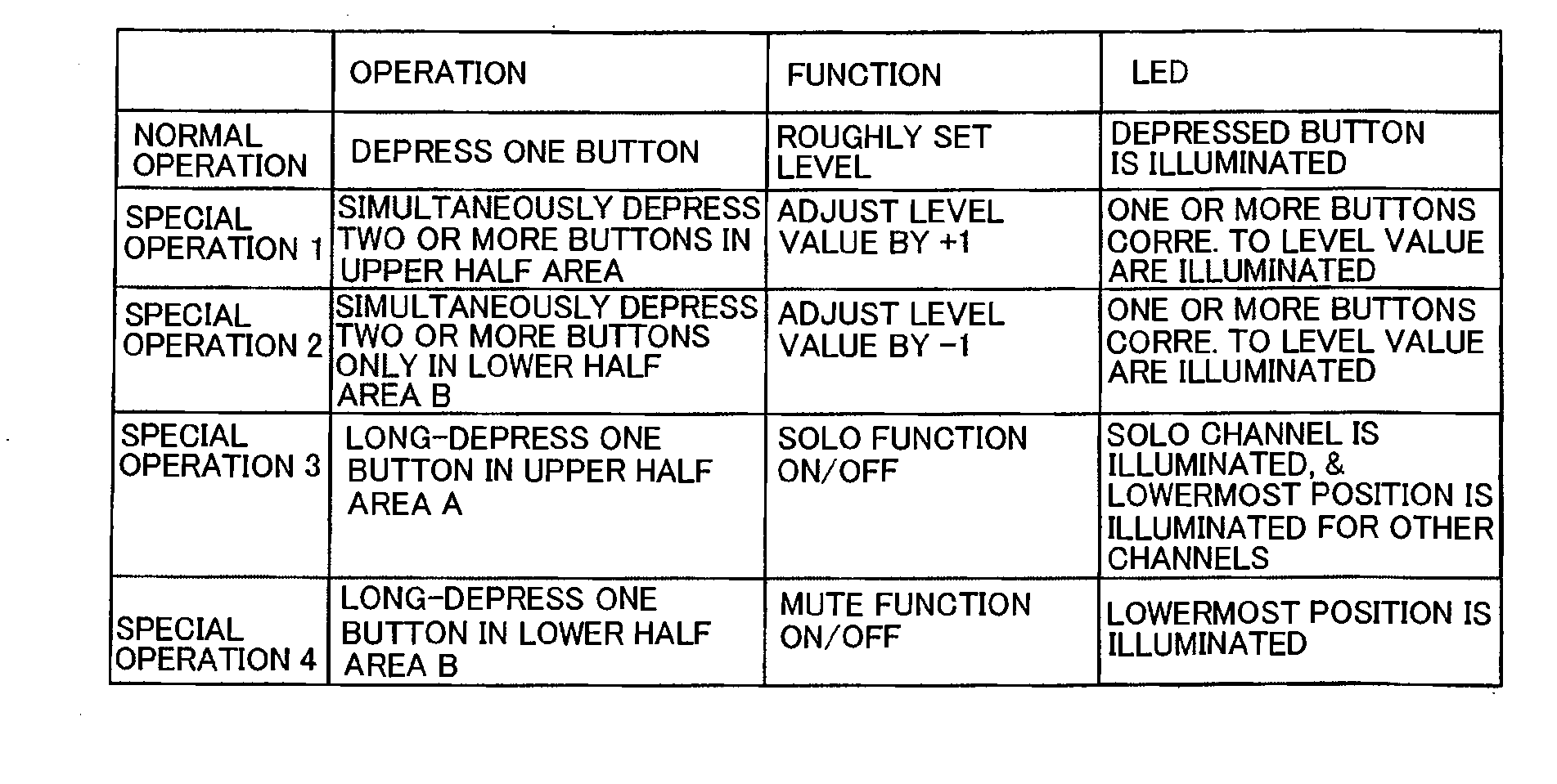
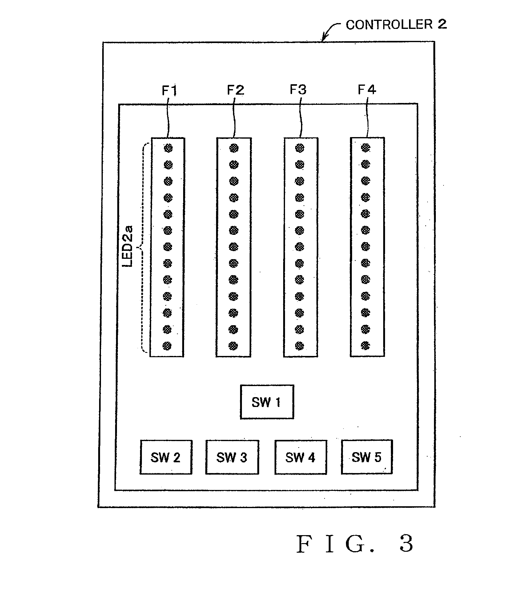
[0027]The fader F1 includes the plurality of LEDs 2a provided inside the touch pad thereof for displaying a current level setting along the longitudinal axis, and the touch pad is divided into two areas: an upper half area A; and a lower half area B. In the first embodiment, four styles: (1) normal operation; (2) first-type special operation; (3) second-type special operation; and (4) third-type special operation are defined as the operation styles of the fader F1.

[0028](1) Normal Operation: When the user touches one point of the touch pad of the fader with its finger, or touches one point of the touch pad and then slides its finger on and along the touch pad continuously (i.e., without releasing the finger from the touch pad), such user's operation is determined to be the normal operation, so that the level of the channel assigned to the fader having that touch pad can be adjusted in response to the normal operation. As such normal operation is performed, the LED 2a at the touched ...

second embodiment

[0043]As shown in FIG. 9, the fader F1′ includes nine LED-equipped push buttons 2b arranged linearly vertically. In the illustrated example of FIG. 9, the level is adjustable in nine steps with the nine LED-equipped push buttons 2b. The level can be increased by 4 (adjusted by +4) per push button 2b; namely, levels corresponding to multiples of four in a range of values 0 to 32 can be set with the nine LED-equipped push buttons 2b. Namely, the fader F1′ is constructed as a plural-button type level controller, and the controller 2 includes four such faders F1′ to F4′ of the aforementioned construction.

[0044]The second embodiment of the fader F1′ is divided into two areas: an upper half area A; and a lower half area B. As the operation styles of the fader F1′ are defined five styles: (1) normal operation; (2) first-type special operation; (3) second-type special operation; (4) third-type special operation; and (5) fourth-type special operation.

[0045](1) Normal Operation: When the user...


PUM


Abstract

It is determined whether user's operation performed on a control is normal or special operation. A function of increasing or decreasing a value of a parameter assigned to the control is performed if the user's operation is the normal operation. Another function, different from the function of increasing or decreasing a value of a parameter, is performed if the user's operation is the special operation. The control comprises, for example, a touch pad provided with a display device for displaying a current operating position of the control. If a user touches one point of the pad with its finger or touches one point of the pad and then continuously slides its finger on and along the pad, such user's operation is determined to be the normal operation. If the user touches or taps two or more points of the pad, such user's operation is determined to be the special operation.

Description

BACKGROUND[0001]The present invention relates to controllers for manipulating or operating parameters related to audio signal processing.[0002]In the field of audio signal processing apparatus using a computer, it has heretofore been known to perform audio processing, such as recording, editing, mixing etc. of performance data, through digital signal processing. Apparatus, such as mixers, which are constructed to adjust a plurality of tone signals, have not only a function of adjusting sound volume settings of individual channels via faders or knobs, but also a function of, in response to operation of a given button, sounding a particular channel (i.e., generating a tone for the particular channel, or setting the particular channel in a solo mode) or muting the particular channel (or setting the particular channel in a mute mode). Some of such apparatus have, in addition to the aforementioned functions, a function of returning a sound volume setting to an initial value or reference ...

Claims


Application Information

Patent Timeline
Patent Type & Authority Applications(United States)
IPC IPC(8): H03G3/02
CPCG06F3/0484G06F3/0488H04S2400/15H04S7/00H04R3/00G11B27/034H04H60/04
Inventor KAMIHARA, MASANORI
Owner YAMAHA CORP
Learn More