
Signal processing circuit and method

Active Publication Date: 2008-05-15
SONY CORP
View PDF5 Cites 13 Cited by
  • Summary
  • Abstract
  • Description
  • Claims
  • Application Information

AI Technical Summary

Benefits of technology

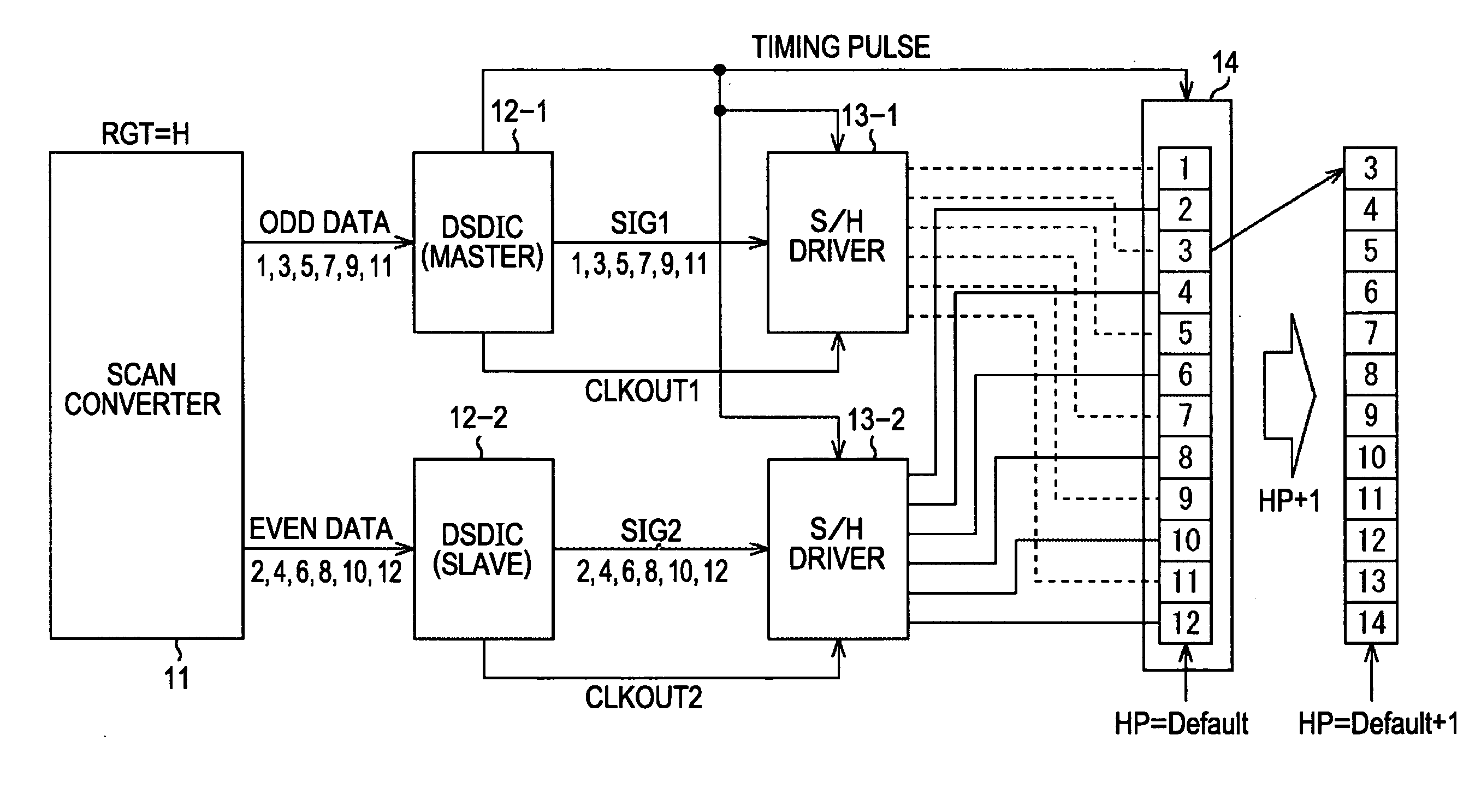
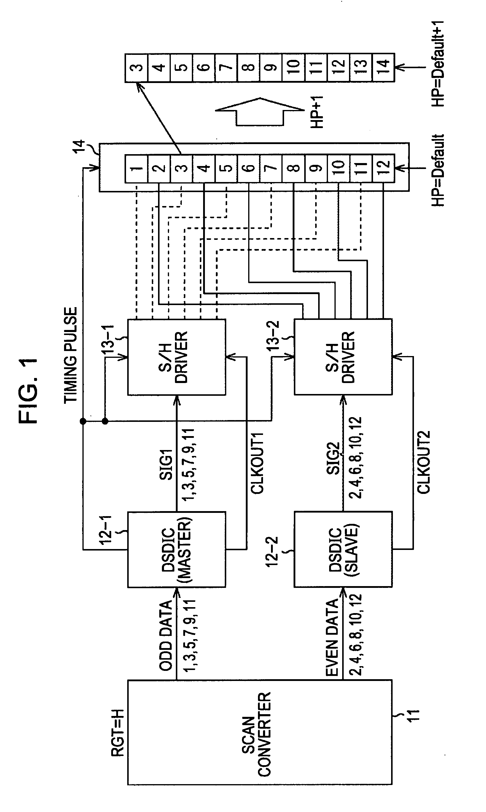
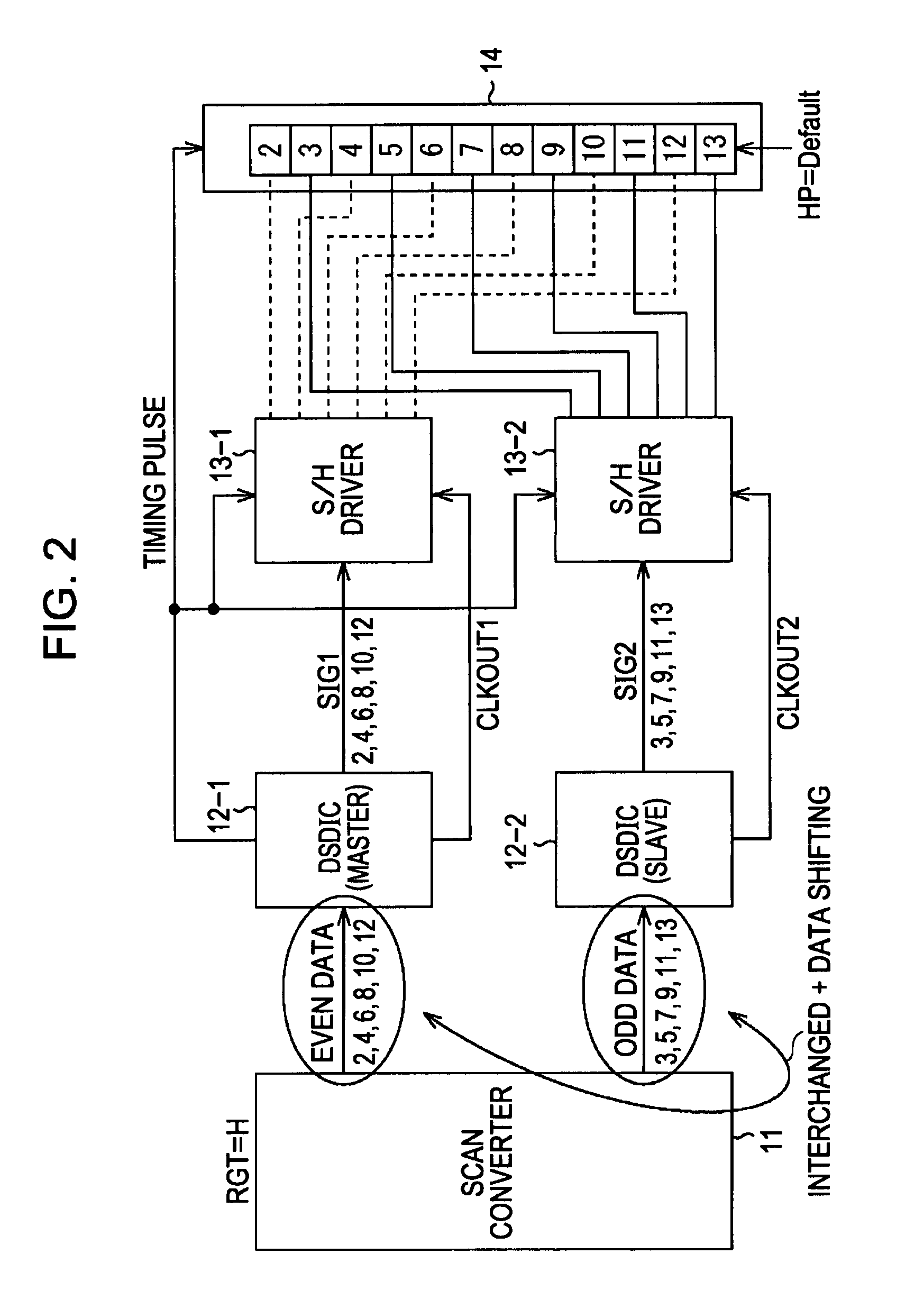
[0050]According to an embodiment of the present invention, positional adjustment in increments of single dots, and correction processing in increments of single dots can be readily performed even in the event of employing multiple signal processing circuits as a signal processing system of a display apparatus.

Problems solved by technology

As described above, in the event of employing multiple digital signal processing circuits as a signal processing system of a liquid crystal display apparatus, in the past, unless interchanging of data and shifting of data are performed at the previous stage before a picture signal is input to the digital signal processing circuits, adjustment has not been able to be performed in increments of single dots.

Method used


Image

  • Signal processing circuit and method
  • Signal processing circuit and method
  • Signal processing circuit and method

Examples


Embodiment Construction

[0070]Before describing embodiments of the present invention, the correspondence between the features of the claims and the specific elements disclosed in embodiments of the present invention is discussed below. This description is intended to assure that embodiments supporting the claimed invention are described in this specification. Thus, even if an element in the following embodiments is not described as relating to a certain feature of the present invention, that does not necessarily mean that the element does not relate to that feature of the claims. Conversely, even if an element is described herein as relating to a certain feature of the claims, that does not necessarily mean that the element does not relate to the other features of the claims.

[0071]A signal processing circuit according to an embodiment of the present invention is a signal processing circuit (e.g., liquid crystal display system in FIG. 5) configured to process a picture signal to output to a display unit mad...


PUM


Abstract

A signal processing circuit includes: multiple digital-signal processing units operating in parallel each including a selecting unit for selecting one of multiple systems of input picture signals, a double-speed converting unit for writing the data equivalent to one field of the picture signal selected by the selecting unit in field memory, and simultaneously reading the data equivalent to one field from the field memory twice at double speed, thereby converting the frequency of the picture signal into double speed, a reading unit for reading the picture signal converted into double speed by the double-speed converting unit and temporarily stored in line memory, and a correction processing unit for subjecting the picture signal read by the reading unit to predetermined correction processing; and a control unit for performing the selection control of the multiple systems of picture signals, and the read position control of a picture signal from the line memory.

Description

CROSS REFERENCES TO RELATED APPLICATIONS[0001]The present invention contains subject matter related to Japanese Patent Application JP 2006-308181 filed in the Japanese Patent Office on Nov. 14, 2006, the entire contents of which are incorporated herein by reference.BACKGROUND OF THE INVENTION[0002]1. Field of the Invention[0003]The present invention relates to a signal processing circuit and method, and particularly, relates to a signal processing circuit and method which facilitate positional adjustment and correction processing in increments of single dots, and so forth, even in the event of employing multiple signal processing circuits as a display apparatus signal processing system.[0004]2. Description of the Related Art[0005]With a display apparatus in which pixels are disposed in a matrix shape, such as an active matrix type liquid crystal display (LCD), apparatus, a digital signal processing circuit (DSD (Digital Signal Driver), ID (Integrated Circuit)) made up of the MOS pro...

Claims


Application Information

Patent Timeline
IPC IPC(8): H04N9/64
CPCG09G3/3688G09G2310/08G09G2320/0204G09G2360/18G09G2340/0435G09G2340/0478G09G2320/0247
Inventor KATO, EIJIFUJIKI, TASUKUHIRAKAWA, TAKASHI
Owner SONY CORP
Learn More