Coordinate measuring apparatus
- Summary
- Abstract
- Description
- Claims
- Application Information
AI Technical Summary
Benefits of technology
Problems solved by technology
Method used
Image
Examples
Example
First Embodiment
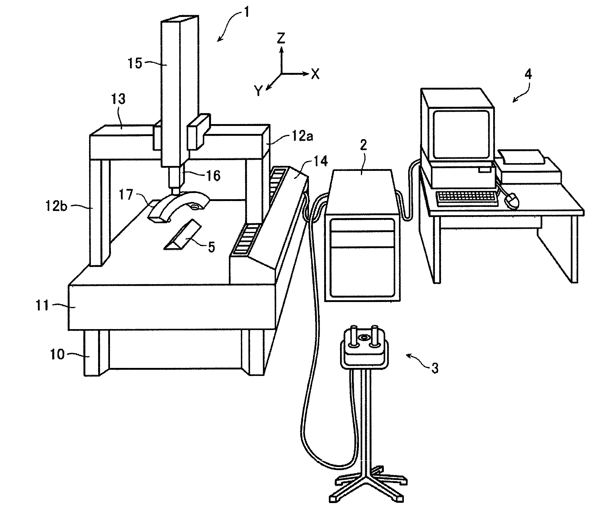
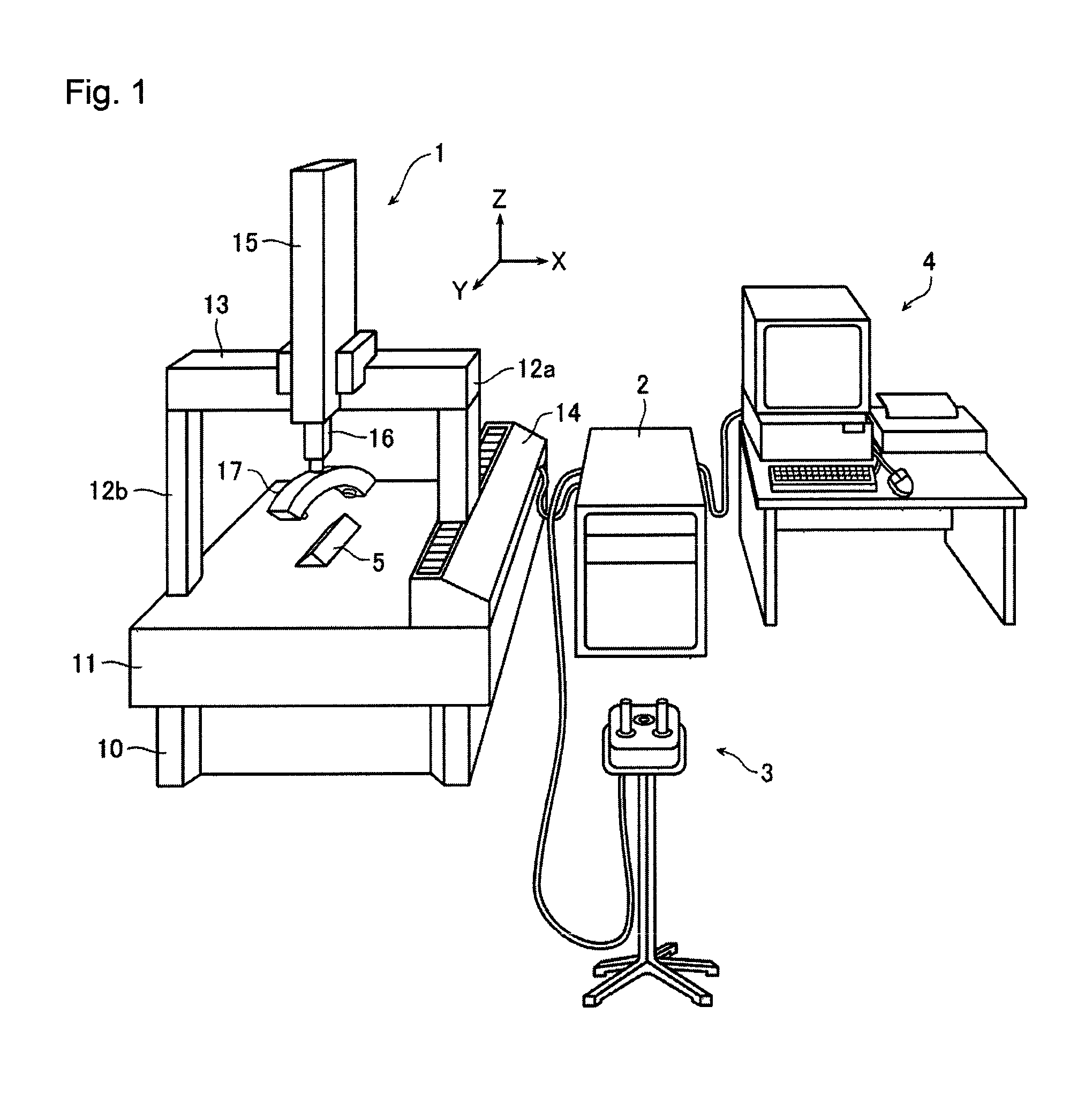
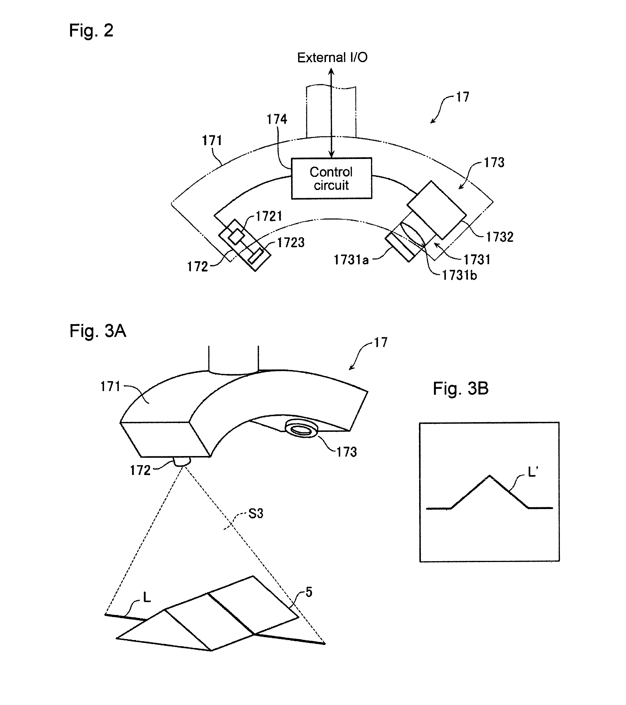
[0036]Hereafter, a coordinate measuring apparatus according to a first embodiment of the present invention is described in detail with reference to the drawings. FIG. 1 is an overall view of a system configuring a coordinate measuring apparatus according to the first embodiment. The coordinate measuring apparatus is configured by providing a non-contact-type optical probe 17 according to the present embodiment as a measurement probe of a coordinate measuring apparatus 1. The coordinate measuring apparatus is configured by a drive control apparatus 2 controlling driving of the coordinate measuring apparatus 1 and also capturing necessary measurement coordinate values from the coordinate measuring apparatus 1; an operation panel 3 for manually operating the coordinate measuring apparatus 1 via the drive control apparatus 2; and a host system 4 compiling / executing a parts program which gives instructions for a measurement procedure performed by the drive control apparat...
Example
Second Embodiment
[0054]Hereafter, a coordinate measuring apparatus according to a second embodiment of the present invention is described in detail with reference to the drawings. FIG. 9 is a flow chart describing a coordinate measurement method according to the present embodiment. The coordinate measurement method according to the present embodiment differs in that first an operation mode selection process is performed (step S1), and a first operation mode (step S2) or a second operation mode (step S3) is selected in response to the selection operation and the light intensity of the emitting optical system 172 is adjusted. The first operation mode is, for example, a manually operated measurement mode in which the probe is manually operated to carry out the measurement, while the second operation mode is, for example, an automatically operated measurement mode in which the probe is automatically operated to carry out the measurement. In the first operation mode, adjustment of the in...
Example
Third Embodiment
[0063]Hereafter, a coordinate measuring apparatus according to a third embodiment of the present invention is described in detail with reference to the drawings. The coordinate measuring apparatus according to the present invention is configured in a manner basically similar to the coordinate measuring apparatus according to the first embodiment. However, a method of adjusting the light intensity of the emitting optical system 172 is different.
[0064]FIG. 12 is a flow chart describing the coordinate measuring apparatus according to the present embodiment. In the present embodiment, emitted light is emitted at the work piece 5 during measurement and verification is performed as to whether incident light is received in the image capture elements arranged in the image capture region 321 (step S301); in a case where the incident light is received, the image capture apparatus 173 is set to a measurement mode (step S302); and the incident light being emitted from the emitti...
PUM
 Abstract
Description
Claims
Application Information
 - R&D
- Intellectual Property
- Life Sciences
- Materials
- Tech Scout
- Unparalleled Data Quality
- Higher Quality Content
- 60% Fewer Hallucinations
Browse by: Latest US Patents, China's latest patents, Technical Efficacy Thesaurus, Application Domain, Technology Topic, Popular Technical Reports.
© 2025 PatSnap. All rights reserved.Legal|Privacy policy|Modern Slavery Act Transparency Statement|Sitemap|About US| Contact US: help@patsnap.com


