Tissue closing device

Inactive Publication Date: 2009-10-29
TERUMO KK
View PDF14 Cites 17 Cited by
  • Summary
  • Abstract
  • Description
  • Claims
  • Application Information

AI Technical Summary

Benefits of technology

[0007]According to the present invention, when the restriction for retaining the actuating member (first elastic member) in the active state is canceled (when the actuating member is put into actuation), the closure and the lock member are moved relative to each other by the restoring force of the first elastic member and the deformation portion of the closure is automatically deformed, in the condition where the closure is lo

Problems solved by technology

This insertion of an instrument such a catheter into a blood vessel is normally performed through a puncture formed by dissecting or puncturing the femoral region After the therapeutic treatment is completed, it is necessary to perform a stanching operation to stop the bleeding through the puncture However, since the blood pressure upon bleeding (bleeding blood pressure) from the femoral artery is relatively high, it is oftentimes necessary for a person involved in the med

Method used


Image

  • Tissue closing device
  • Tissue closing device
  • Tissue closing device

Examples


first embodiment

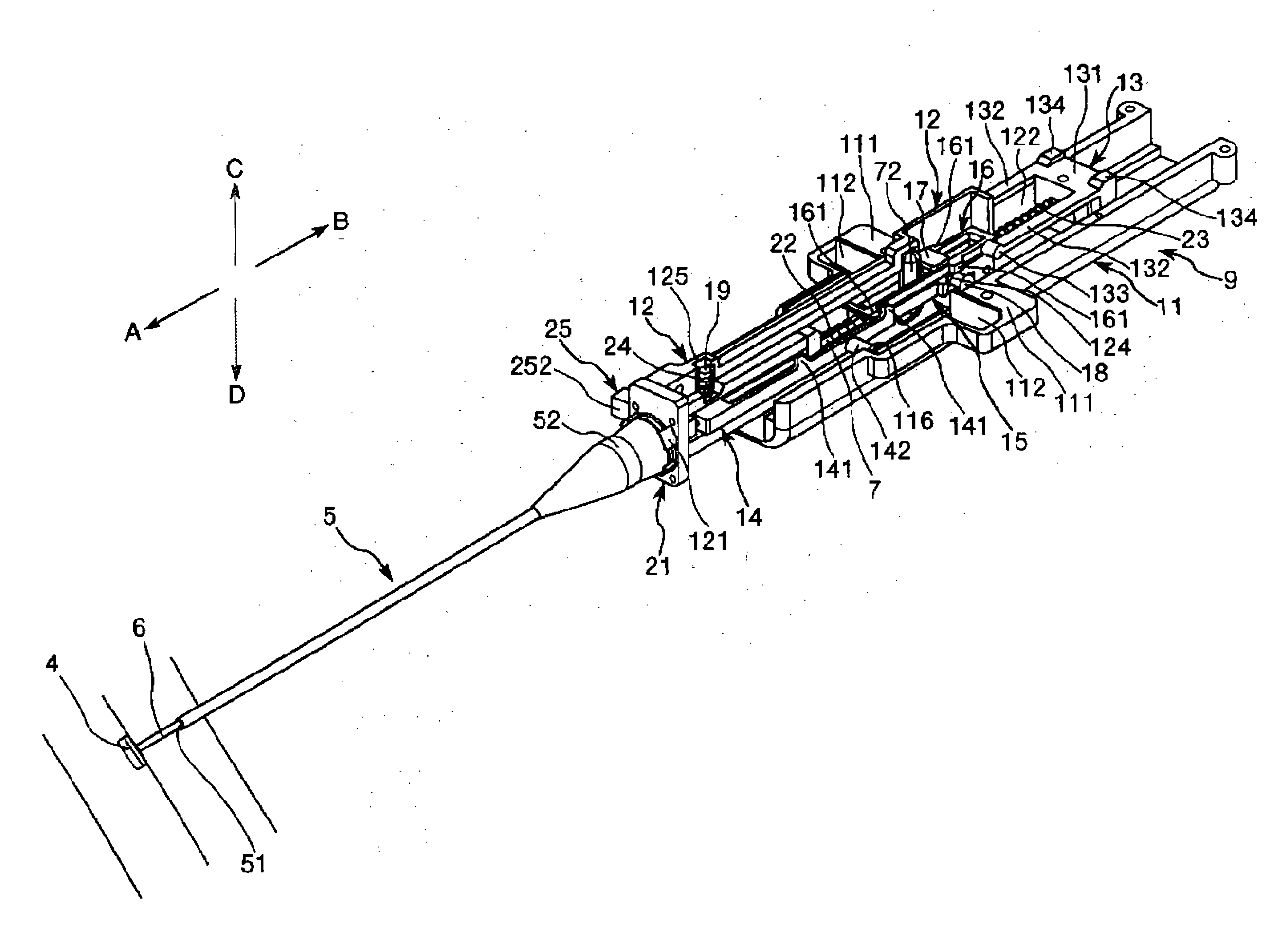
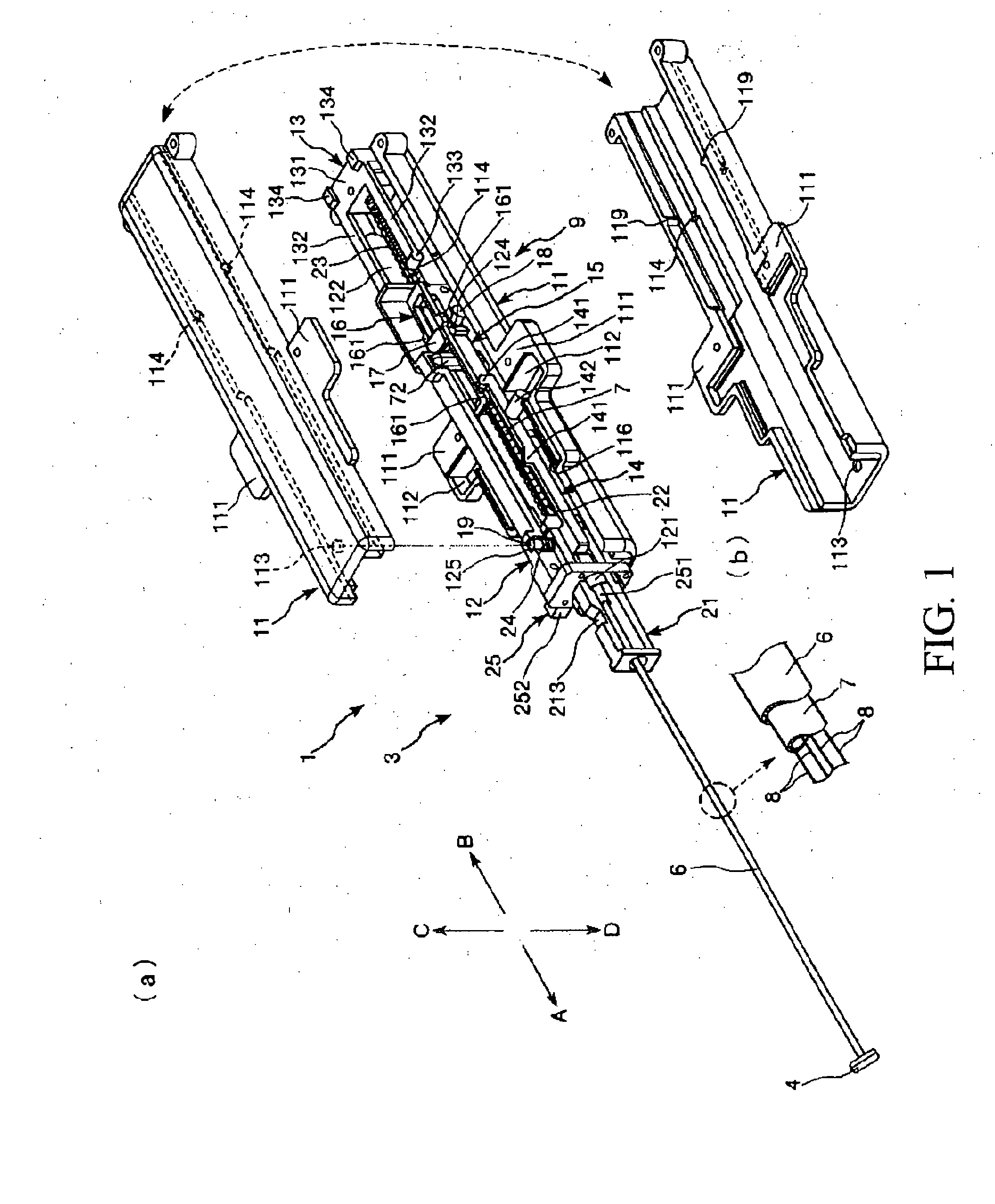
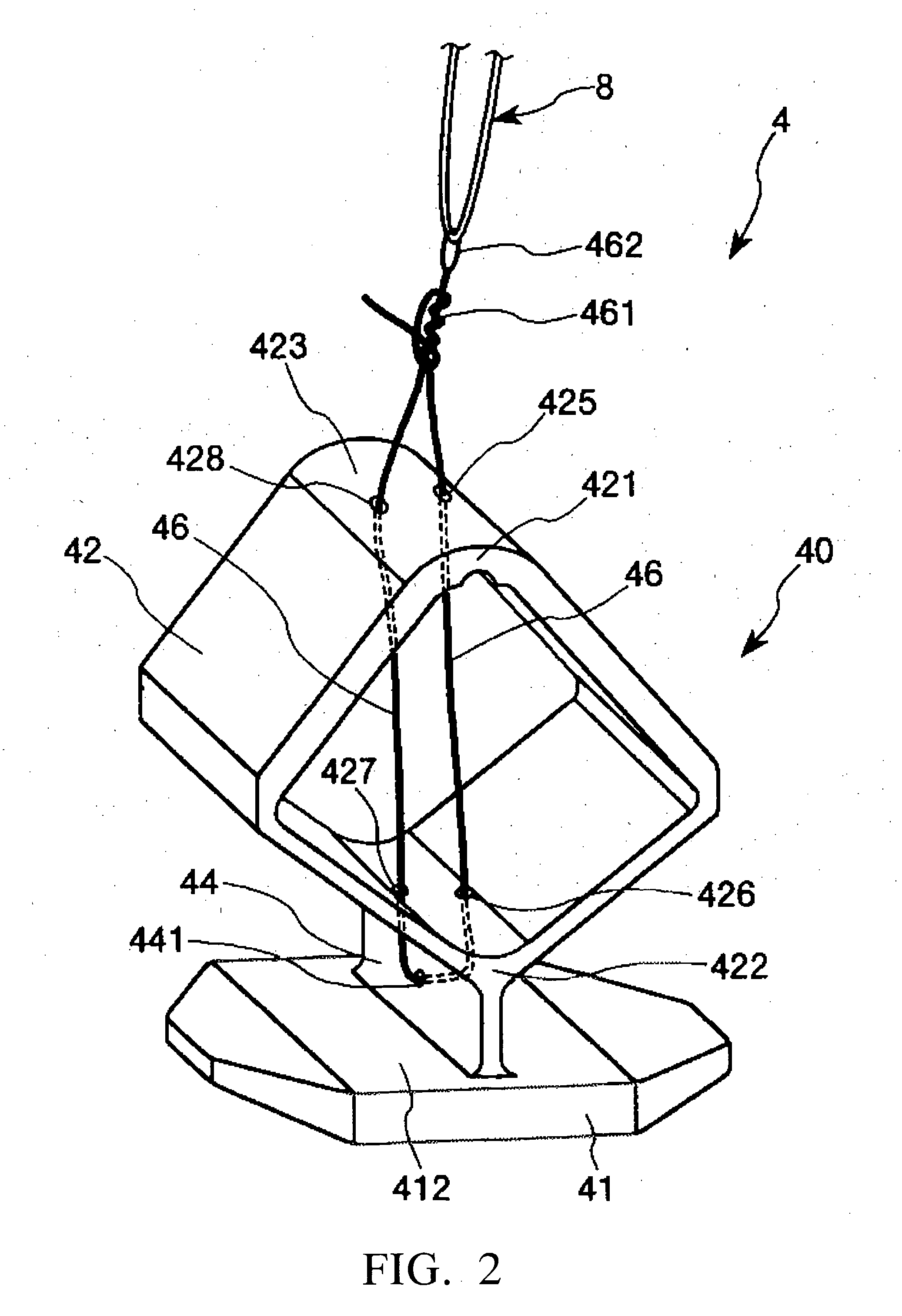
[0048]FIG. 1 shows perspective views showing a first embodiment of the tissue closing device, in which FIG. 1(a) A is an overall perspective view, and FIG. 1(b) is a perspective view showing the inner portion side of an upper half of a casing FIG. 2 is a perspective view of a closure in the tissue closing device shown in FIG. 1FIG. 3 is an illustration of one example of a knot of the closure in the tissue closing device shown in FIG. 1FIG. 4 is an illustration of another example of the knot of the closure in the tissue closing device shown in FIG. 1FIG. 5 is an exploded perspective view (members (component parts)) of the tissue closing device shown in FIG. 1FIG. 6 shows perspective views of a distal end portion of the tissue closing device shown in FIG. 1, in which FIG. 6(a) is an outlook view, and FIG. 6(b) as a perspective drawing (showing the condition where a cover tube is removed) FIG. 7 is a perspective view showing a thread support portion, a pin and a thread in the tissue cl...

second embodiment

[0162]Now, a second embodiment of the tissue closing device according to the present invention will be described below

[0163]FIG. 26 is a perspective view of the second embodiment (locked condition) of the tissue closing device according to the present invention, FIG. 27 is a sectional view of a part on the distal side of a handling portion in the tissue closing device shown in FIG. 26, FIG. 28 is a perspective view of the second embodiment (unlocked condition) of the tissue closing device according to the present invention, and FIG. 29 is a sectional view of a part on the distal side of the handling portion in the tissue closing device shown in FIG. 28

[0164]Incidentally, for convenience of description, in FIGS. 26 to 29, the direction of arrow A will be referred to as “distal”, the direction (hand side) of arrow B as “proximal”, the direction of arrow C as “upper”, and the direction of arrow D as “lower”, in the following description

[0165]Now, the tissue closing device 1 according t...

third embodiment

[0176]Now, a third embodiment of the tissue closing device according to the present invention will be described below

[0177]FIG. 30 is a perspective view illustrating the third embodiment of the tissue closing device according to the present invention, FIG. 31 is an exploded perspective view (showing the members (component parts)) of the tissue closing device shown in FIG. 30, FIGS. 32(a) and 32(b) show a thread support portion, a pin, and a thread in the tissue closing device shown in FIG. 30, FIG. 32(a) is a perspective view, and FIG. 32(b) is a schematic plan view Besides, FIGS. 32(a) to 39(b) are perspective views for illustrating the operations (movements) of the tissue closing device shown in FIG. 30, in which 32(a), 33(a), 34(a), 35(a), 36(a), 37(a), 38(a), and 39(a) in each figure shows the handling portion side, and 32(b), 33(b), 34(b), 35(b), 36(b), 37(b), 38(b), and 39(b) shows the distal end portion side

[0178]Incidentally, in FIGS. 30 and 33(a) to 39(a), an upper cover of...


PUM


Abstract

A tissue closing device includes an elongate arrangement device of which a distal end portion can penetrate an opening penetrating an living tissue membrane and which has a handling portion on the proximal side, and a clip which is detachably retained at a distal end portion of the arrangement device and which closes the opening. The arrangement device includes a retaining member for detachably retaining the clip and pulling the clip in the proximal direction, a cover tube, and a fixed tube. The handling portion has a first elastic member. When a restriction for maintaining the coil spring in a deformed state is canceled, the thread is moved to the proximal direction by the restoring force of the coil spring in the condition where the clip is locked to a distal end portion of the fixed tube, and the clip is pulled in the axial direction by the thread, whereby a deformation portion is deformed.

Description

TECHNICAL FIELD[0001]The present invention generally relates to a tissue closing device More specifically, The present invention pertains to a living body tissue closing device[0002]Low-invasion operations carried out by inserting a device for diagnosis or treatment, such as a catheter, into a blood vessel or some other tissue are known and performed on a quite often basis For example, to treat a constriction of the coronary artery of the heart, it is necessary to insert a device such as a catheter into a blood vessel in order to perform therapeutic on the constriction[0003]This insertion of an instrument such a catheter into a blood vessel is normally performed through a puncture formed by dissecting or puncturing the femoral region After the therapeutic treatment is completed, it is necessary to perform a stanching operation to stop the bleeding through the puncture However, since the blood pressure upon bleeding (bleeding blood pressure) from the femoral artery is relatively high...

Claims


Application Information

Patent Timeline
IPC IPC(8): A61B17/10A61B17/08
CPCA61B17/0057A61B2017/00575A61B2017/00606A61B2017/0496A61B2017/00623A61B2017/0475A61B2017/00619A61B17/00
Inventor MARUYAMA, TOMOJIKAWAURA, MASAKATSUNAKAMOTO, RYOU
Owner TERUMO KK
Why Eureka
Try Eureka