
Multifunction printer, printing system, and still image printing program

a printing system and printer technology, applied in the direction of image enhancement, digital output to print units, instruments, etc., can solve the problems of inability to print any still image, insufficient image as a whole,

Inactive Publication Date: 2008-09-25
BROTHER KOGYO KK
View PDF18 Cites 15 Cited by
  • Summary
  • Abstract
  • Description
  • Claims
  • Application Information

AI Technical Summary

Benefits of technology

[0007]An object of the present invention is to provide a multifunction printer which makes it possible to print a satisfactory still image by correcting any defective portion even when the defective portion is present in a part of a still image selected by a user.
[0013]The combined image, in which a part of the base image is corrected, is automatically printed on the second printing medium such that the user views the list indication of the thumbnail images of the plurality of pieces of the still image data printed on the first printing medium and the user merely marks the base image selection mark and the correction position mark to the first printing medium to allow the scanner to read the printing medium. Therefore, it is unnecessary to perform any special operation which is not performed by the user during the ordinary image printing in order to print the combined image. Therefore, even in the case of the user who is weak in the equipment operation, it is possible to easily and conveniently print the combined still image of the desired scene in the moving image.
[0015]In the multifunction printer of the present invention, when the base image selection mark and the correction position mark are marked respectively to the thumbnail images which are different from each other, the correction data-extracting section may extract, as the correction image data, the still image data corresponding to the thumbnail image marked with the correction position mark. When the correction position mark is marked by the user to the distinct thumbnail image which is different from the thumbnail image marked with the base image selection mark, the correction data-extracting section judges that the instruction is made to correct the base image data by using the still image data corresponding to the correction position mark. The still image data, which corresponds to the thumbnail image marked with the correction position mark, is extracted as the correction image data. The data, which is included in the correction image data and which corresponds to the correction position mark, is cut out as the correction data. Therefore, the user can simultaneously perform the designation of the correction image data and the correction position by merely marking the correction position mark directly to the thumbnail image of the still image data to be used to correct the base image.
[0017]In the multifunction printer of the present invention, when the correction position mark is marked onto the thumbnail image, the data, which is included in the correction image data and which corresponds to an area including the correction position mark on the thumbnail image, may be cut out as the correction data by the correction data-extracting section. According to this arrangement, the data, which corresponds to the area marked with the correction position mark, of the thumbnail image, is cut out as the correction data. Therefore, the user can easily designate the correction area by directly marking the correction position mark to the area in which the base image is intended to be corrected, on the thumbnail image.
[0018]In the multifunction printer of the present invention, when the correction position mark is marked to surround a part of the thumbnail image, the data, which corresponds to the area surrounded by the correction position mark of the thumbnail image, may be cut out as the correction data from the correction image data by the correction data-extracting section. When the correction position mark is marked to surround a part of the thumbnail image as described above, the correction data-extracting section judges that the area surrounded by the correction position mark is the area to be corrected, and the data of the area is cut out as the correction data. In this case, the user can instruct the correction area more finely by surrounding only the area intended to be corrected.

Problems solved by technology

However, the device described in U.S. Pat. No. 7,221,470 has the following problem.
That is, if any defective portion (unfavorite point for the user) is present in only a part of a still image, for example, such that a person is photographed at that moment with eyes closed in the selected image selected by the user, then the image is not satisfactory as a whole, even when the image is satisfactory in all points except for the above.
It is impossible to print any still image which is favorite for the user.

Method used


Image

  • Multifunction printer, printing system, and still image printing program
  • Multifunction printer, printing system, and still image printing program
  • Multifunction printer, printing system, and still image printing program

Examples


first embodiment

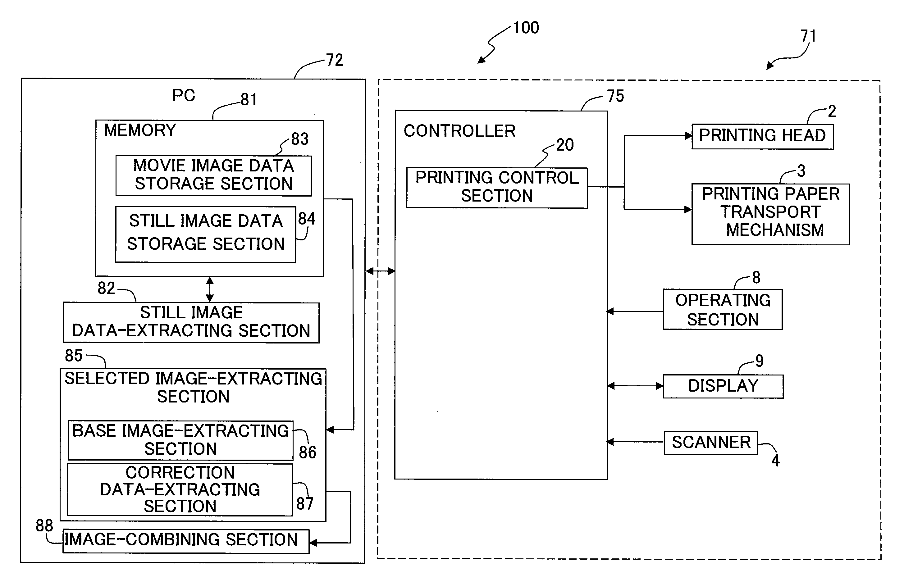
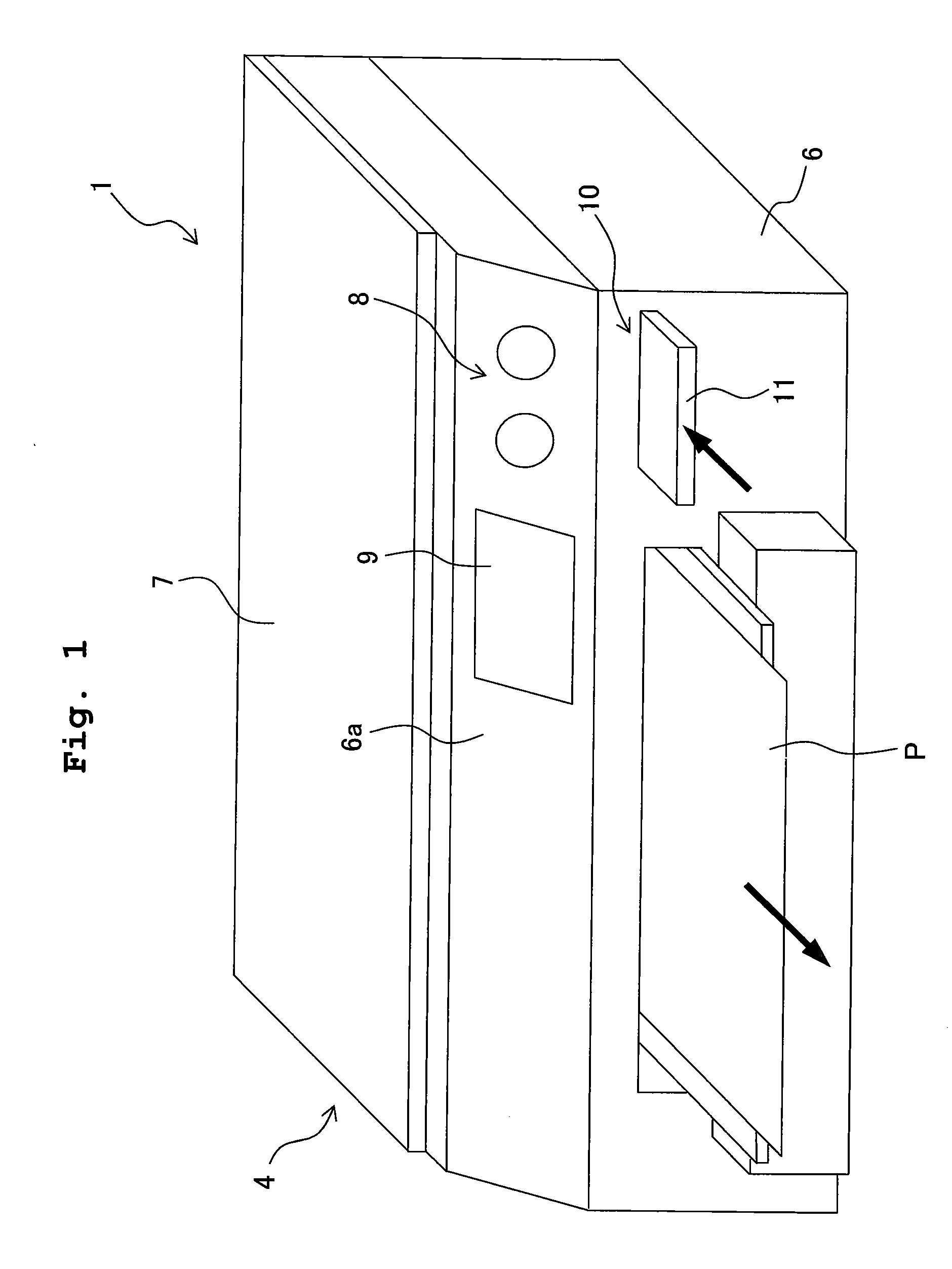
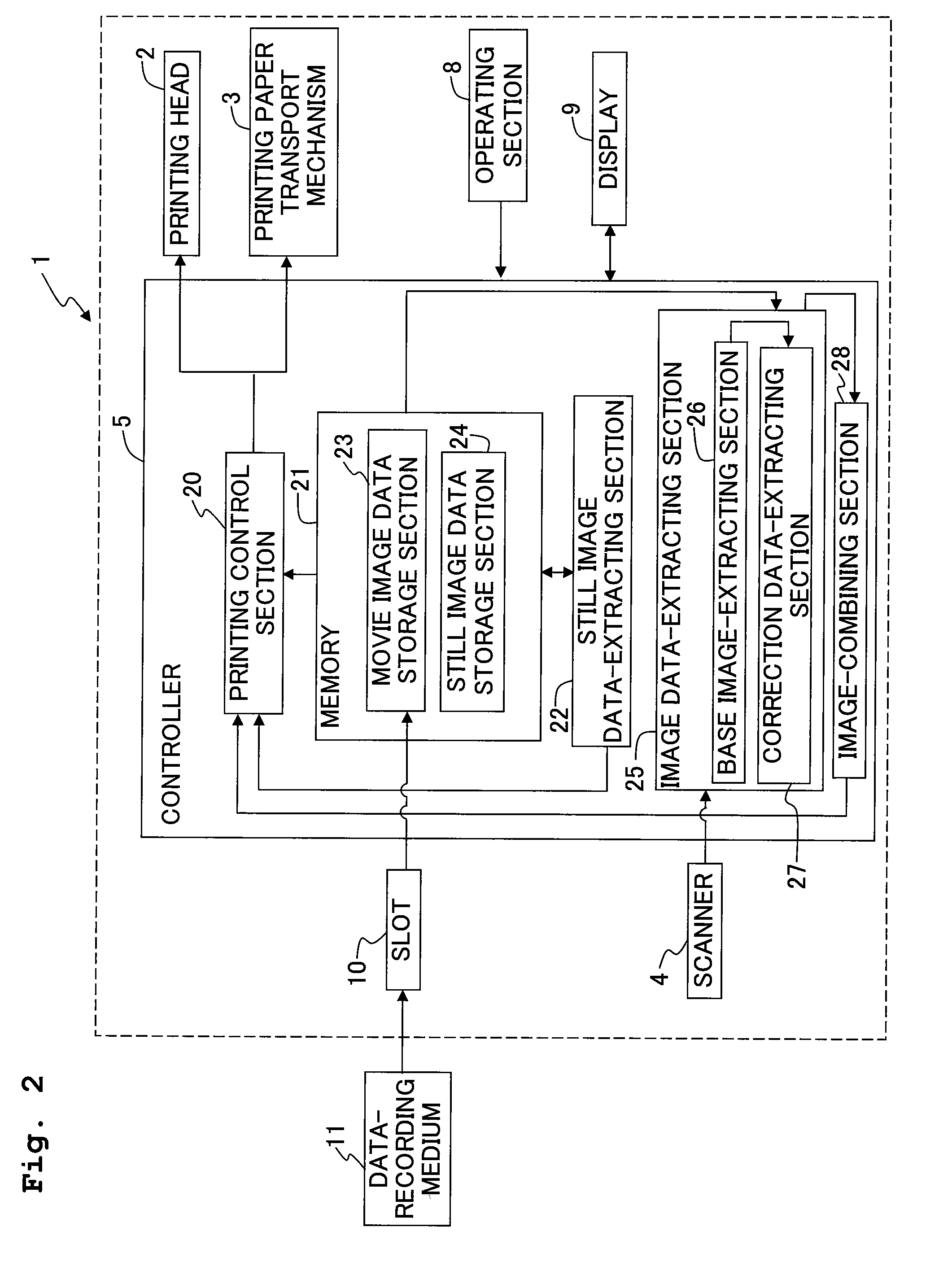
[0057]Additionally, the multifunction printer 1 of the first embodiment has the following unique feature which is not possessed by any conventional multifunction machine. At first, a plurality of pieces of the still image data are extracted from the movie image data inputted from the data-recording medium 11 in response to the request from the user via the operating section 8 so that thumbnail images 30 (reduced images) of the plurality of pieces of the still image data are printed on the printing paper P (thumbnail image-printing process: see FIG. 5).

[0058]Further, when the printing paper sheet P1 is read by the scanner 4 in a state in which a base image selection mark 31 for selecting a base image and a correction position mark 32 for instructing a correction area as a part of the base image are marked to the printing paper sheet P1 (first printing medium) printed with the thumbnail images 30 (see FIG. 6), the base image data corresponding to the base image selection mark 31 is co...

first modified embodiment

[0086]A first modified embodiment will be explained, in which the following modification is applied to the first embodiment explained above. In the first embodiment described above, the printing head 2 simultaneously prints the plurality of check boxes 34 corresponding to the plurality of thumbnail images 30 respectively in order that the user easily marks the base image selection mark 31, when the plurality of thumbnail images 30 are printed on the printing paper sheet P1 (see FIGS. 6 and 7). However, it is possible to recognize the thumbnail image 30 selected by the mark 31 from the position at which the base image selection mark 31 is marked, irrelevant to the presence or absence of the check boxes 34. Therefore, it is not necessarily indispensable that the printing head 2 should print the check boxes 34 together with the plurality of thumbnail images 30.

[0087]When the check box 34 is not printed on the printing paper sheet P1 as described above, then the user may directly write ...

second modified embodiment

[0088]Next, a second modified embodiment will be explained. The number of pieces of the still image data extracted from one piece of the movie image data is large depending on the total time of the movie image data and / or the time interval at which the still image data are extracted. All of the thumbnail images 30, which correspond to the pieces of the still image data, cannot be printed on one printing paper sheet P in some cases. In such a situation, the thumbnail images 30 of one piece of the movie image data are printed over a plurality of printing paper sheets P1.

[0089]In this case, at first, the still image data-extracting section 22 extracts, from the movie image data, the plurality of pieces of the still image data while dividing them into a plurality of groups. The printing control section 20 judges on which printing paper sheet P1 the thumbnail image 30 of a certain piece of the still image data is to be printed, from the group to which the still image data belongs. The pr...


PUM


Abstract

A multifunction printer includes a scanner; a memory which stores a plurality of still image data; a printing head which prints, on a first printing medium, thumbnail images corresponding to the plurality of the still image data; an image data-extracting section which extracts a base image data and a correction image data when the first printing medium is read by the scanner after the predetermined base image selection mark has been marked by a user to one of the plurality of thumbnail images printed on the first printing medium and the predetermined correction position mark has been marked to a partial area of the thumbnail image and which cuts out, from the correction image data, correction data corresponding to the area marked with the correction position mark, and an image-combining section which combines the base image data with the correction data to generate combined image data.

Description

CROSS REFERENCE TO RELATED APPLICATION[0001]The present application claims priority from Japanese Patent Application No. 2007-074061, filed on Mar. 22, 2007, the disclosure of which is incorporated herein by reference in its entirety.BACKGROUND OF THE INVENTION[0002]1. Field of the Invention[0003]The present invention relates to a multifunction printer, a printing system including the multifunction printer, and a still image printing program to be used for the multifunction printer.[0004]2. Description of the Related Art[0005]A technique has been hitherto known, in which a piece of still image data of a desired scene is extracted from a piece of movie image data composed of a plurality of pieces of still image data arranged in a chronological order, and an image of the still image data (still image) is printed on a printing medium. For example, an image output device, which is described in U.S. Pat. No. 7,221,470 (corresponding to Japanese Patent Application Laid-open No. 2003-26466...

Claims


Application Information

Patent Timeline
IPC IPC(8): G06F15/00
CPCH04N1/00355H04N1/00366H04N2201/0094H04N1/2158H04N1/387H04N1/00374
Inventor SUGAHARA, HIROTOGOTO, KAZUMA
Owner BROTHER KOGYO KK
Learn More