Shielded wire-grounding construction

a shielding wire and construction technology, applied in the direction of communication cables, coupling device connections, cables, etc., can solve the problem that resist welding cannot be performed in the production line, and achieve the effect of reducing the size of the wire harness, reducing the risk of arcing, and high shielding performan

Inactive Publication Date: 2011-07-14
AUTONETWORKS TECH LTD +2
View PDF14 Cites 13 Cited by
  • Summary
  • Abstract
  • Description
  • Claims
  • Application Information

AI Technical Summary

Benefits of technology

[0084]As described above, in the present invention, the drain wires of the shielded wire and the ground wire are connected to each other by the crimping connection by using the intermediate crimping terminal or by twisting the drain wires and the ground wire or through the joint bus bar. Therefore as compared with the case in which the drain wires and the ground wire are connected to each other by welding the portion of the drain wire to be connected and the portion of the ground wire to be connected to each other, it is possible to decrease the lead-out length of the drain wire to 40 mm at the shortest. Because it is possible to decrease the peeling length of the shielded wire by the above-described length, it is possible to enhance the shielding performance of shielded wire.
[0085]Further the peeling length of the sheath of the shielded wire and the length of the exposed portion of each drain wire are short. Therefore in connecting a plurality of the drain wires to the ground wire, it is unnecessary to perform a tape-winding operation to align the front ends of the drain wires with each other. Thus it is possible to decrease the number of operation steps.
[0086]The length of each drain wire from the rear end to the connected portion at which the drain wires and the ground wire are connected with each other or to the joint connector is short. Therefore the length from the position at which the shielded wire is peeled to the connector into which the terminal disposed at the end of the core electric wire is inserted and locked thereto is short. Thus it is possible to accommodate the connected portion at which the drain wires and the ground wire are connected with each other or the joint connector inside the connector cover mounted on the connector without doubling the drain wires in an excess portion thereof Consequently it is unnecessary to hold the connected portion at which the drain wires and the ground wire are connected with each other or the joint connector on the shielded wire by winding a tape around the peripheral surface of the shielded wire and restrain the wire harness composed of one shielded wire or a plurality of the bundled shielded wires from becoming locally large and make the wire harness slim.

Problems solved by technology

Thus the resistance welding cannot be performed in a production line.
Another problem is that because the peeling length of the sheath is long, it is necessary to band the drain wires together with the tape 3 to align the front ends of the drain wires with one another before the resistance welding work is performed.

Method used


Image

  • Shielded wire-grounding construction
  • Shielded wire-grounding construction
  • Shielded wire-grounding construction

Examples


first embodiment

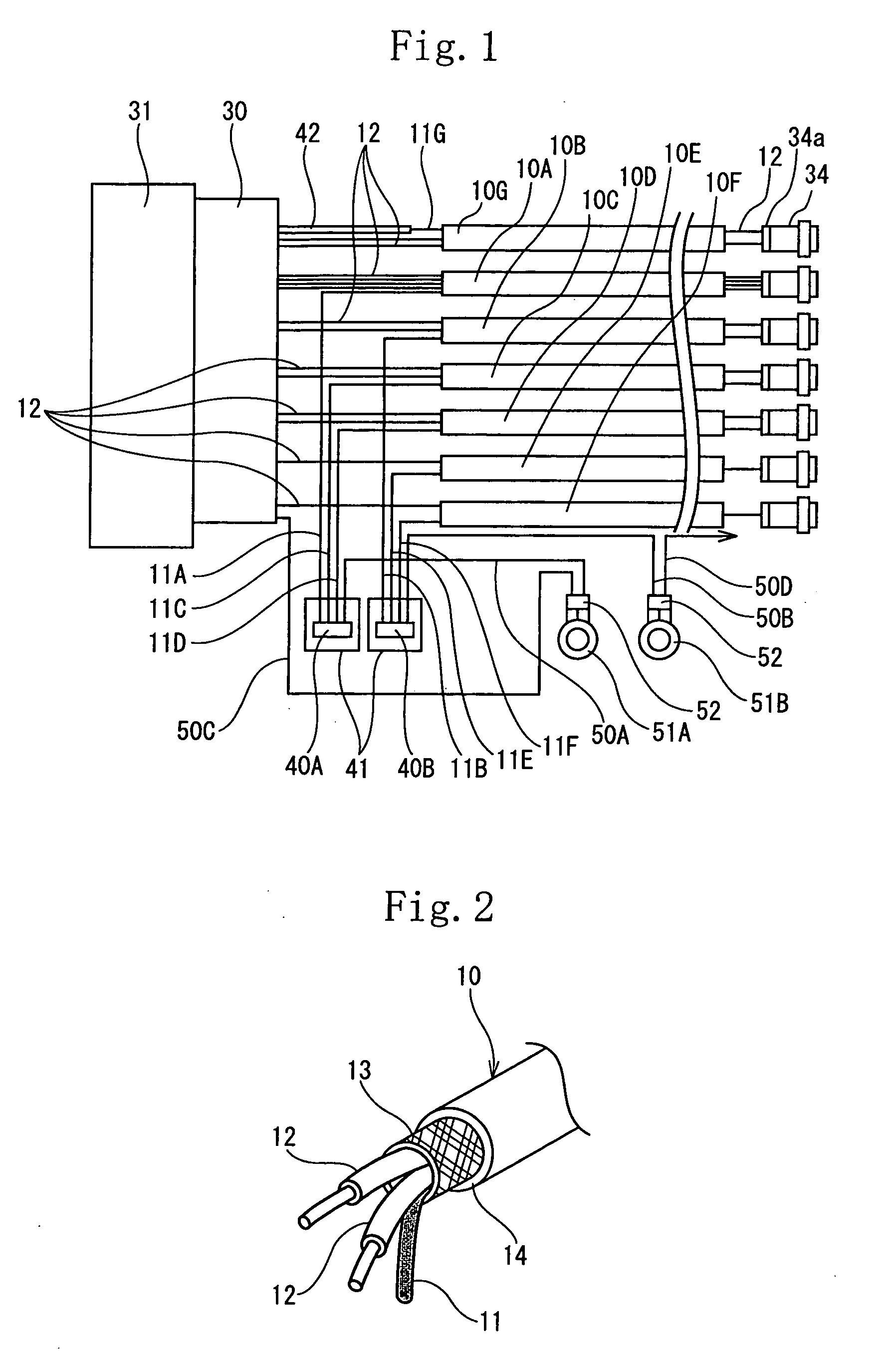
[0132]FIGS. 1 through 6 show the present invention.

[0133]As shown in FIG. 4, a wire harness W / H composed of a plurality of shielded wires 10 and an electric wire 20 other than the shielded wire 10 is wired in an engine room of a car. An end of the wire harness W / H is connected to one connector 30 connected to a fuel injection control apparatus 31 by fitting the connector 30 in the fuel injection control apparatus 31.

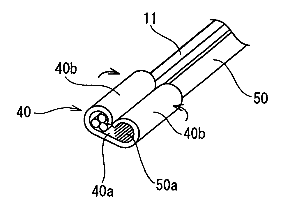
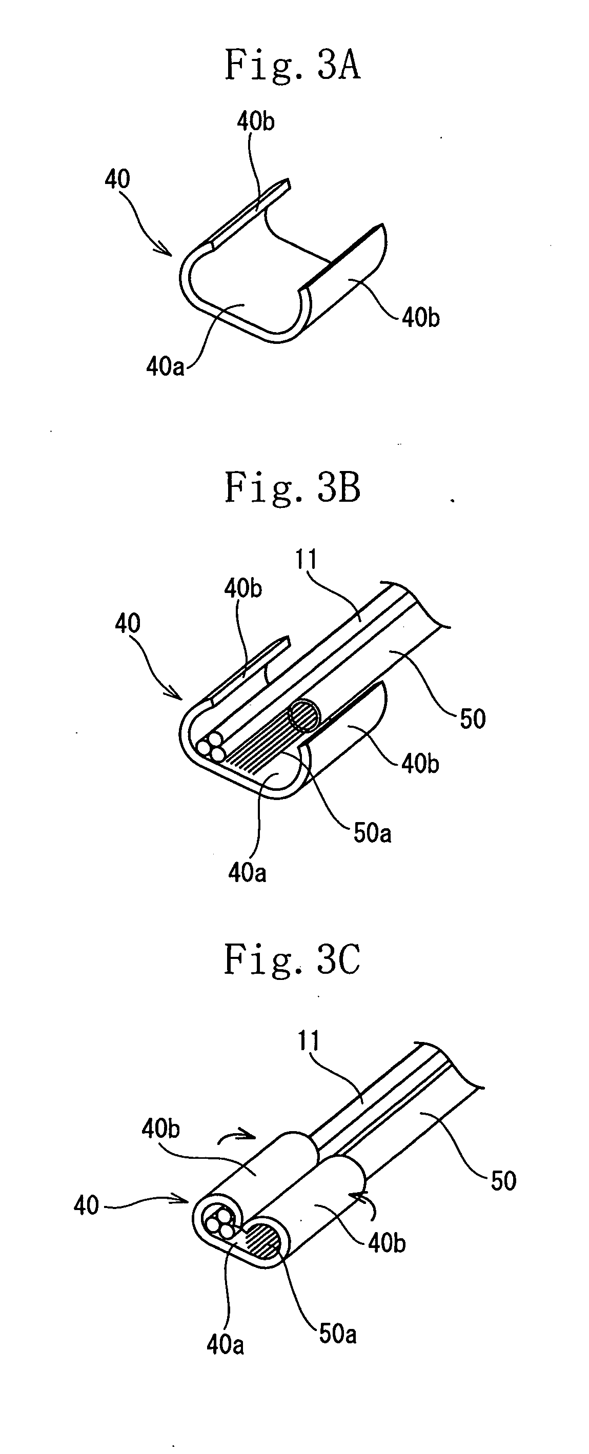
[0134]As shown in FIG. 2, the shielded wire 10 is composed of one or a plurality of core wires 12 consisting of insulated coated electric wires which constitute one or a plurality of signal wires and one drain wire 11. The drain wire 11 and the core wires 12 are coated with a shielding layer 13 consisting of a metal foil or a tube of a braided metal and a sheath 14 made of an insulating resin material, with the shielding layer 13 coated with the sheath 14. The drain wire 11 is brought into contact with the shielding layer 13 to make the shielding layer 13 and drain wire ...

fourth embodiment

[0197]FIGS. 16 and 17 show the present invention.

[0198]In the fourth embodiment, the drain wire 11 of the shielded wire 10 and the ground wire 50 are connected with each other through a joint bus bar 61 disposed inside a joint connector 60.

[0199]More specifically, crimping terminals 62, 63 are connected to a lead-out side end of each drain wire 11 lead out from the shielded wire 10 and to conductors disposed at other end of the ground wire 50 disposed at a side opposite to one end thereof connected with a ground terminal. The crimping terminals 62, 63 have female terminals 62a, 63a respectively connected with the joint bus bar 61 at one end thereof and crimping barrels 62b, 63b at the other end thereof. The crimping barrels 62b and 63b are caulked to the drain wires 11 and the ground wire 50 to connect the drain wires 11 and the ground wire 50 with each other by the crimping connection.

[0200]The joint bus bar 61 connecting the drain wires 11 and the ground wire 50 to each other has ...


PUM

PropertyMeasurementUnit
lengthaaaaaaaaaa
peeling lengthaaaaaaaaaa
lengthaaaaaaaaaa

Abstract

The lead-out side end of a drain wire led out from a shield wire and either a conductor exposed to one end of a ground wire, to the other end of which a ground terminal is connected, or a conductor exposed to one end of a ground wire, to the other end of which a connector receiving terminal is connected, are collectively connected together by crimping by using a U-shape cross-sectioned intermediate crimp terminal formed by a pair of opposed barrels, or connected by twisting them together, or connected through a joint bus bar.

Description

[0001]This is a Continuation of application Ser. No. 12 / 309,232 filed Jan. 12, 2009, which in turn is a which is a National Phase of Application No. PCT / JP2007 / 064424 filed Jul. 23, 2007. The disclosure of the prior applications is hereby incorporated by reference herein in its entirety.BACKGROUND[0002]The present invention relates to a shielded wire-grounding construction. More particularly the present invention is intended to provide a slim construction for connecting a drain wire lead out from an end of the shielded wire and a ground wire to each other.[0003]Conventionally it is necessary to insert a core electric wire consisting of one or a plurality of insulated coated electric wires into a braided tube made of metal fibers or into a metal foil for shielding use and connect the shielded wire composed of the braided metal tube or the metal foil covered with a sheath (insulating coating) to a ground wire.[0004]In Japanese Patent Application Laid-Open No. 2000-268893 (patent docum...

Claims


Application Information

Patent Timeline
Patent Type & Authority Applications(United States)
IPC IPC(8): H01B11/06
CPCH01R4/184H01R4/726H01R9/034H01R9/0512H01R2201/26H01R13/52H01R24/562H01R2105/00H01R9/0518H01R13/65914
Inventor HAGI, MASAHIROYAMANO, YOSHIAKINISHIMURA, NAOYASAIJO, KATSUTOSHIBABA, HIROTAKAICHIKAWA, MASAHARUYAMADA, AKIRA
Owner AUTONETWORKS TECH LTD
Why Eureka
Try Eureka