Structure of connector

Inactive Publication Date: 2012-10-04
DIN IND
View PDF6 Cites 1 Cited by
  • Summary
  • Abstract
  • Description
  • Claims
  • Application Information

AI Technical Summary

Benefits of technology

[0007]In view of the above discussed, the present invention aims to provide an improved structure of connector that offers excellent protections of conductive terminal against undesired deformation and makes the conductive terminal more capable of bearing external damages.
[0008]An objective of the present invention is to provide a connector, which comprises a positioning section that functions to position and retain elastic segments of a conductive terminal so as to protect the conductive terminal from damage caused by improper insertion of an external terminal pin in an incorrect, deviated direction and which provides an arrangement of elastic segments that provides the conductive terminal with better capable of bearing external damages.
[0009]To achieve the above objective, the present invention provides a connection that comprises a sheath and a conductive terminal that is received in the sheath. The sheath comprises a first sheath member, which has an end forming an expanded flange and an opposite end forming a plurality of elastic segments. The elastic segments form gaps therebetween. The first sheath member is received in a second sheath member. The second sheath member forms a receiving chamber in which the first sheath member is receivable. The second sheath member forms, inside an end thereof, a positioning section on which the elastic segments are positionable. When an external terminal pin is inserted into the second sheath member to engage the conductive terminal, the positioning section retains the elastic segments in position to prevent the insertion of the external terminal pin from being made in an incorrect, deviated direction and thus damaging the conductive terminal. This arrangement provides a solution for the drawbacks that insertion of an external terminal pin into the sheath that is assembled with a conductive terminal may cause undesired deformation of the conductive terminal due to a receiving compartment being made cylindrical and thus lacking of elastic resiliency, that the conductive terminal is incapable of bearing strong external damages, and that the conductive terminal is susceptible to positional shifting.

Problems solved by technology

When an external terminal pin is inserted into the second sheath member to engage the conductive terminal, the positioning section retains the elastic segments in position to prevent the insertion of the external terminal pin from being made in an incorrect, deviated direction and thus damaging the conductive terminal.
This arrangement provides a solution for the drawbacks that insertion of an external terminal pin into the sheath that is assembled with a conductive terminal may cause undesired deformation of the conductive terminal due to a receiving compartment being made cylindrical and thus lacking of elastic resiliency, that the conductive terminal is incapable of bearing strong external damages, and that the conductive terminal is susceptible to positional shifting.

Method used


Image

  • Structure of connector
  • Structure of connector
  • Structure of connector

Examples


Embodiment Construction

[0016]The following descriptions are exemplary embodiments only, and are not intended to limit the scope, applicability or configuration of the invention in any way. Rather, the following description provides a convenient illustration for implementing exemplary embodiments of the invention. Various changes to the described embodiments may be made in the function and arrangement of the elements described without departing from the scope of the invention as set forth in the appended claims.

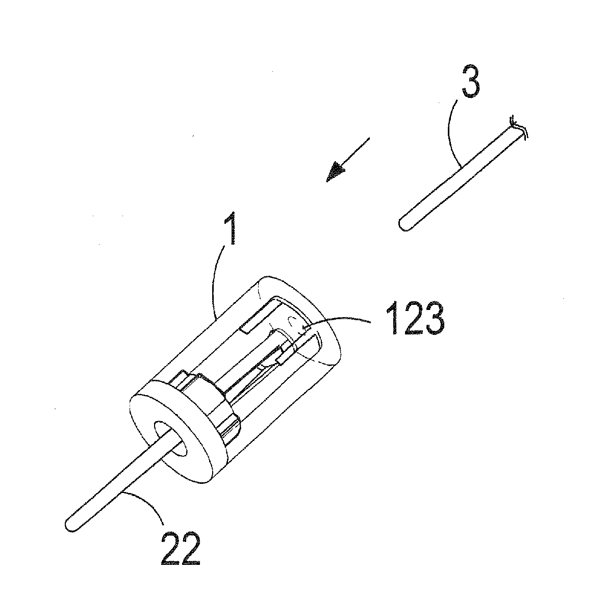
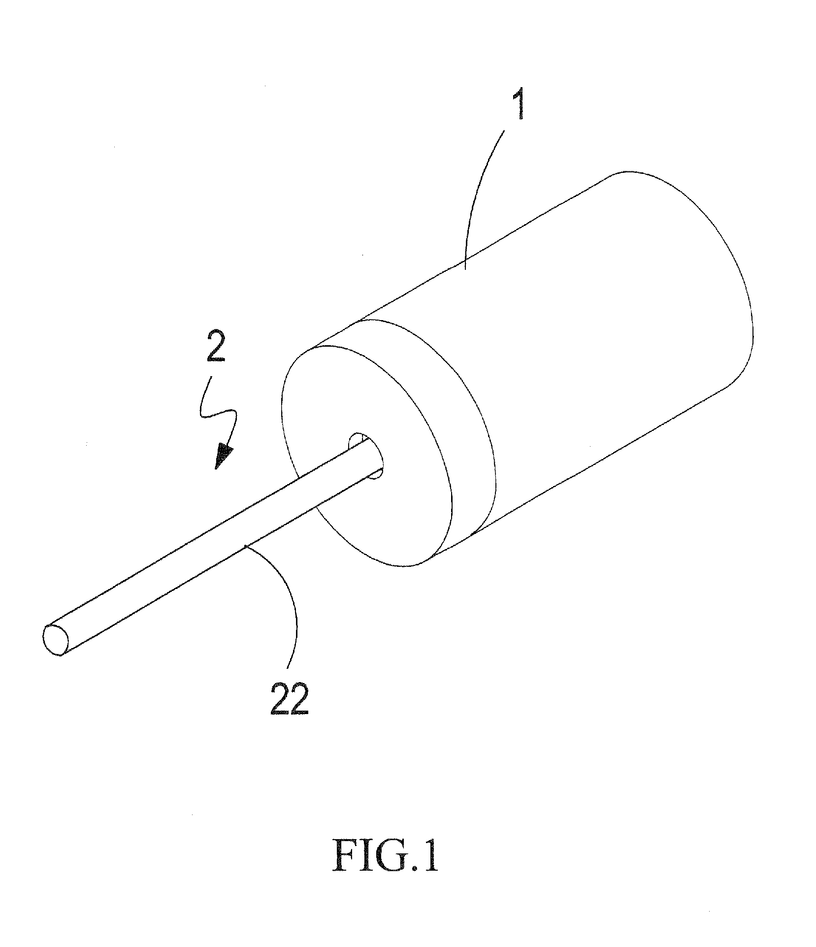
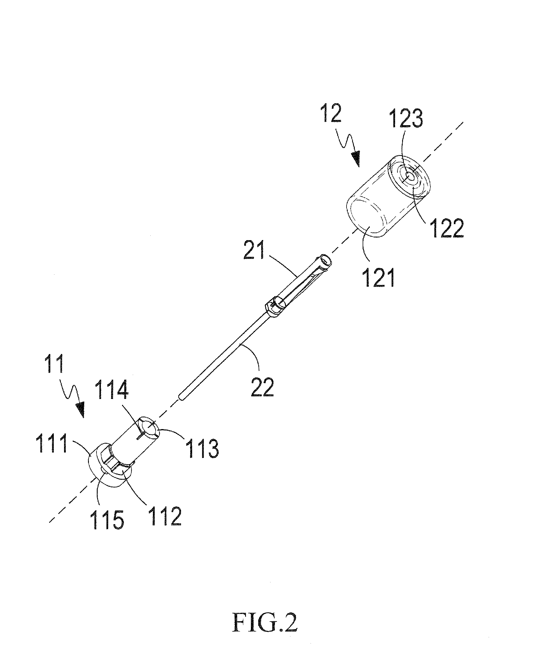
[0017]Referring to FIGS. 1 and 2, which are respectively a perspective view and an exploded view of a preferred embodiment according to the present invention, the drawings clearly show that the present invention provides a connector that comprises a sheath 1 and a conductive terminal 2 that is received in the sheath 1. The conductive terminal 2 comprises a resilient coupling section 21 and a conductive pin 22 connected to the resilient coupling section 21 and extending outside the sheath 1. The shea...


PUM


Abstract

An improved structure of connector includes a sheath and a conductive terminal that is received in the sheath. The sheath includes first and second sheath members. The first sheath member has an end forming a flange and an opposite end forming a plurality of elastic segments. The second sheath member forms a receiving chamber in which the first sheath member is receivable and also forms, inside an end thereof, a positioning section on which the elastic segments are positionable. As such, when an external terminal pin is inserted into the second sheath member to engage the conductive terminal, the positioning section retains the elastic segments in position to prevent the insertion of the external terminal pin from being made in an incorrect, deviated direction and thus damaging the conductive terminal. The arrangement of the elastic segments provides the conductive terminal with better capability of bearing external damages.

Description

(a) TECHNICAL FIELD OF THE INVENTION[0001]The present invention generally relates to a connector, and more particularly to an improved structure of connector that protects a conductive terminal thereof from undesired deformation and makes the conductive terminal more capable of bearing external damages.(b) DESCRIPTION OF THE PRIOR ART[0002]A terminal that functions for connection and electrical conduction must be provided for a communication device, such as a telecommunication connector, a cable connector, or a distributor. The conductive terminal may be of varied category and structure, but has an essential common function of electrical connection and transmission of signal.[0003]A cable connector comprises an enclosure sheath, which is composed of a first sheath member and a second sheath member. The first sheath member has an end that forms a circumferential flange having an expanded diameter and an opposite end forming a receiving compartment for receiving a conductive terminal....

Claims


Application Information

Patent Timeline
IPC IPC(8): H01R13/46
CPCH01R13/502
Inventor HUANG, CHING-KUN
Owner DIN IND
Why Eureka
Try Eureka