Method and Apparatus for Motion Recognition

a technology of motion recognition and motion, applied in image enhancement, image data processing, instruments, etc., can solve the problems of user discomfort in touching the screen, damage to the touch panel,

Active Publication Date: 2012-10-11
SAMSUNG ELECTRONICS CO LTD
View PDF12 Cites 37 Cited by
  • Summary
  • Abstract
  • Description
  • Claims
  • Application Information

AI Technical Summary

Benefits of technology

The present technology relates to analyzing video data for detecting objects or people moving within it. It uses multiple cameras placed at different locations to capture images which can be processed together to create a 3D representation of the scene. This allows for better identification and tracking of individual individuals or groups of people. Additionally, the system calculates how strongly two frames of image data correlate with one another over time, called spatiotemporal correlators. These correlators form a network based on their proximity to other markers in the scene. When there is no significant movement detected, the system checks if any new activity occurs in this network. If there is, it generates a cluster of related markers to track the movements of specific objects. Overall, this approach helps improve accuracy and efficiency when identifying and following targets across various camera angles and distances.

Problems solved by technology

The technical problem addressed in this patent is finding ways to improve the interactions between people and electronics by providing more intuitive and hygienic interfaces. Current methods such as keyboards, mice, and touch panels have limitations including damage from frequent use or discomfort when direct contact with the screen. This needs to change to create better experiences for users.

Method used


Image

  • Method and Apparatus for Motion Recognition
  • Method and Apparatus for Motion Recognition
  • Method and Apparatus for Motion Recognition

Examples


Embodiment Construction

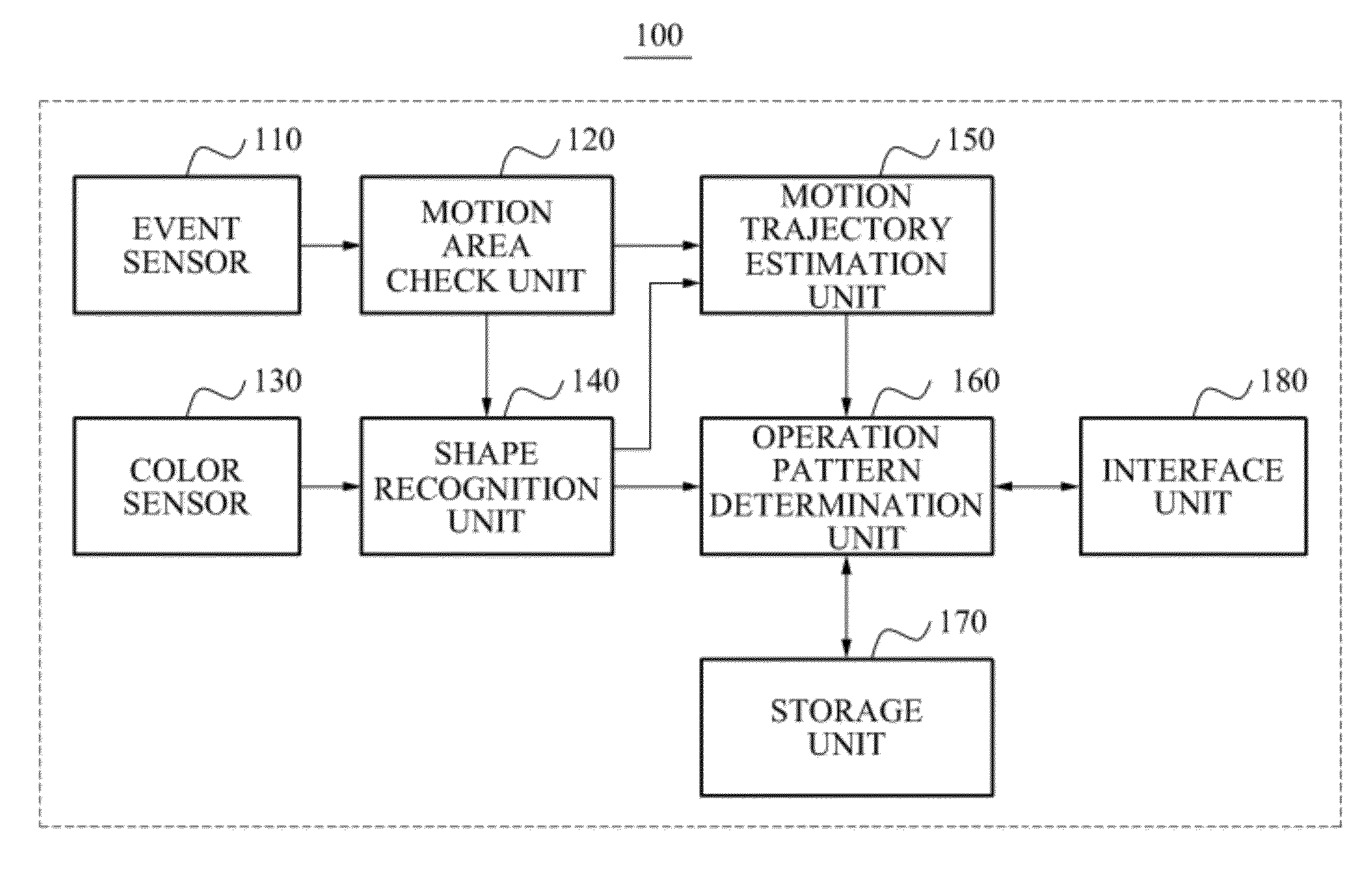
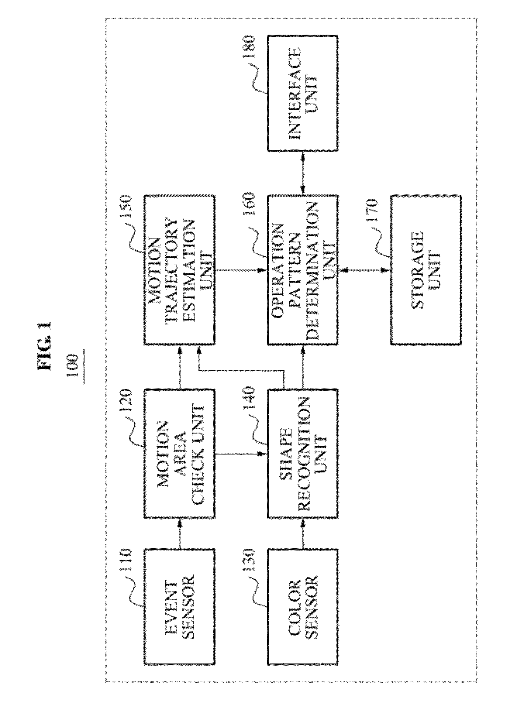
[0035]The following detailed description is provided to assist the reader in gaining a comprehensive understanding of the methods, apparatuses, and / or systems described herein. Accordingly, various changes, modifications, and equivalents of the systems, apparatuses and / or methods described herein will be suggested to those of ordinary skill in the art. Also, descriptions of well-known functions and constructions may be omitted for increased clarity and conciseness FIG. 1 illustrates an example of a motion recognition apparatus 100.

[0036]Referring to FIG. 1, the motion recognition apparatus 100 that recognizes an operation pattern according to a motion of an object includes an event sensor 110, a motion area check unit 120, a color sensor 130, a shape recognition unit 140, a motion trajectory estimation unit 150, an operation pattern determination unit 160, a storage unit 170, and an interface unit 180.

[0037]The event sensor 110 relates to an image sensor that senses a portion of the...


PUM


Abstract

A motion recognition apparatus is provided. The motion recognition apparatus includes an event sensor configured to sense a portion of an object, where a motion occurs, and output events, a color sensor configured to photograph the object and output a color image, a motion area check unit configured to check a motion area which refers to an area where the motion occurs, using spatiotemporal correlations of the events, a shape recognition unit configured to recognize color information and shape information of an area corresponding to the motion area in the color image, a motion estimation unit configured to estimate a motion trajectory using the motion area, the color information, and the shape information, and an operation pattern determination unit configured to determine an operation pattern of the portion where the motion occurs, based on the estimated motion trajectory.

Description


Claims


Application Information

Patent Timeline
Owner SAMSUNG ELECTRONICS CO LTD
Why Eureka
Try Eureka