
Method and Device for Ultraviolet Light Sterilizing

a technology of ultraviolet light and sterilization method, which is applied in the direction of chemical to radiation conversion, disinfection, therapy, etc., can solve the problems of nosocomial infections, large health and financial burden on hospitals, doctors, patients, etc., and achieve the effect of maximizing the irradiation rate of uv ligh

Active Publication Date: 2012-10-18
NOORI GILDA
View PDF21 Cites 41 Cited by
  • Summary
  • Abstract
  • Description
  • Claims
  • Application Information

AI Technical Summary

Benefits of technology

[0006]Given the above deficiencies of prior art, there is a need for a disinfecting and sterilizing device that effectively and efficiently uses UV light to sterilize various objects such as medical or lavatory devices.
[0009]The UV lamp used in the inventive device preferably generates radiation with a wavelength ranging from 200 nm to 290 nm. Radiation with a 254 nm wavelength generally has the optimal germicidal effect.
[0011]Advantageously, the sterilizing device is constructed of reflective materials, or, comprises walls with reflective materials on their surfaces, so as to maximize the irradiation rate of the UV light.

Problems solved by technology

One common problem that hospitals face today is the spread of nosocomial infections.
The nosocomial infections pose a huge health and financial burden on hospitals, doctors, and patients.
People infected by these resistant organisms often have to be hospitalized for extended periods of time and pay for expensive anti-microbial medications.
Furthermore, a significant percentage of infected patients are prone to ultimate health deterioration and potentially fatal consequences.
Poor hand washing, re-use of medical devices, or failure to sterilize the environment, all may increase the chance of distributing the microbial organisms.
Therefore, patients in isolation are often treated using a “disposable” stethoscope, which can provide only limited patient information due to its inferior quality.
The device disclosed in the '233 Patent and the like suffer certain problems by virtue of the structure and materials employed.
For example, the device depicted therein requires a component to uphold the medical apparatus such as stethoscope, thereby entailing unnecessary parts and materials.
Moreover, the materials used for the disclosed device such as clear plastic and glass do not provide effective irradiation due to their transparency quality.

Method used


Image

  • Method and Device for Ultraviolet Light Sterilizing
  • Method and Device for Ultraviolet Light Sterilizing
  • Method and Device for Ultraviolet Light Sterilizing

Examples


Embodiment Construction

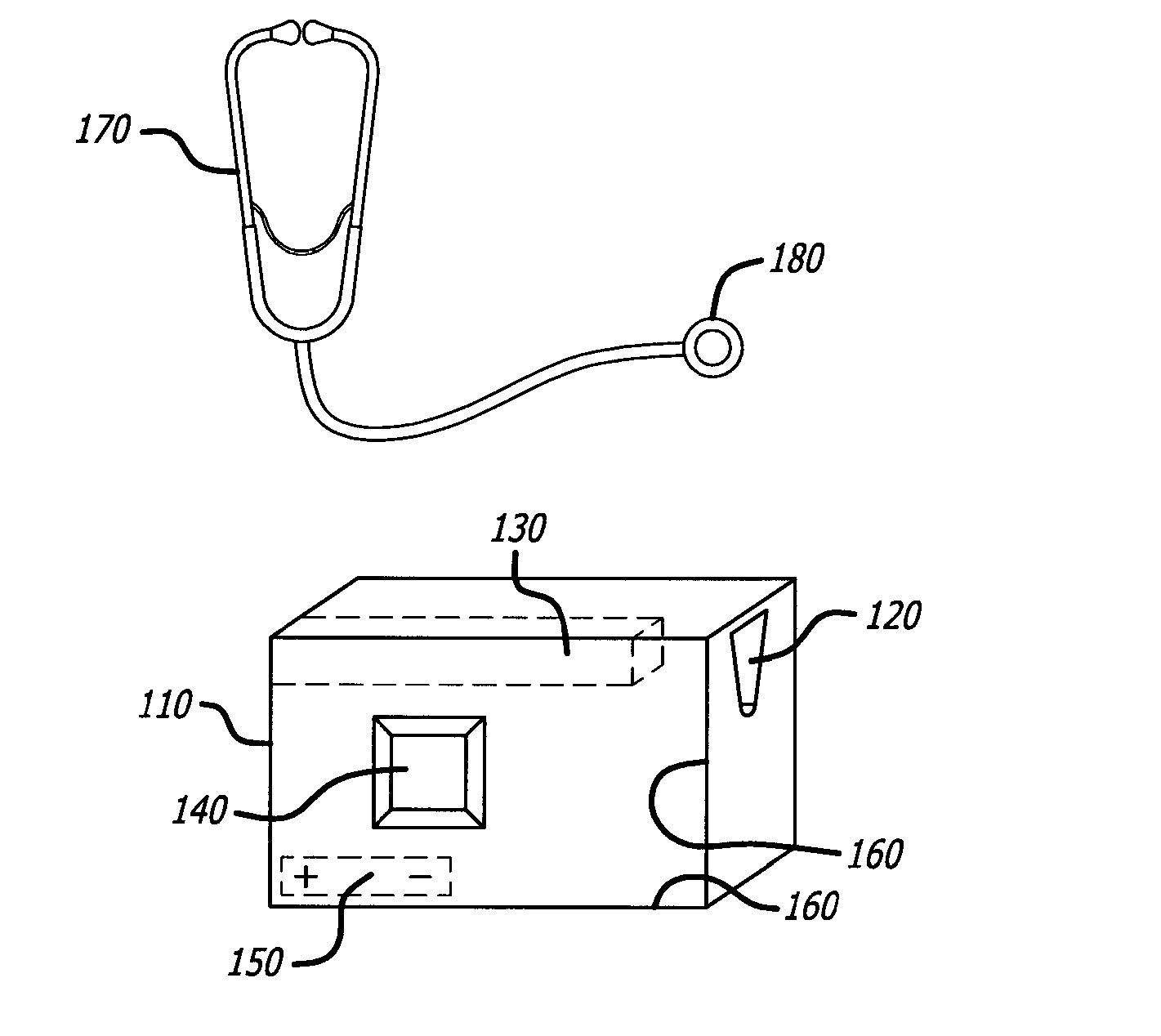
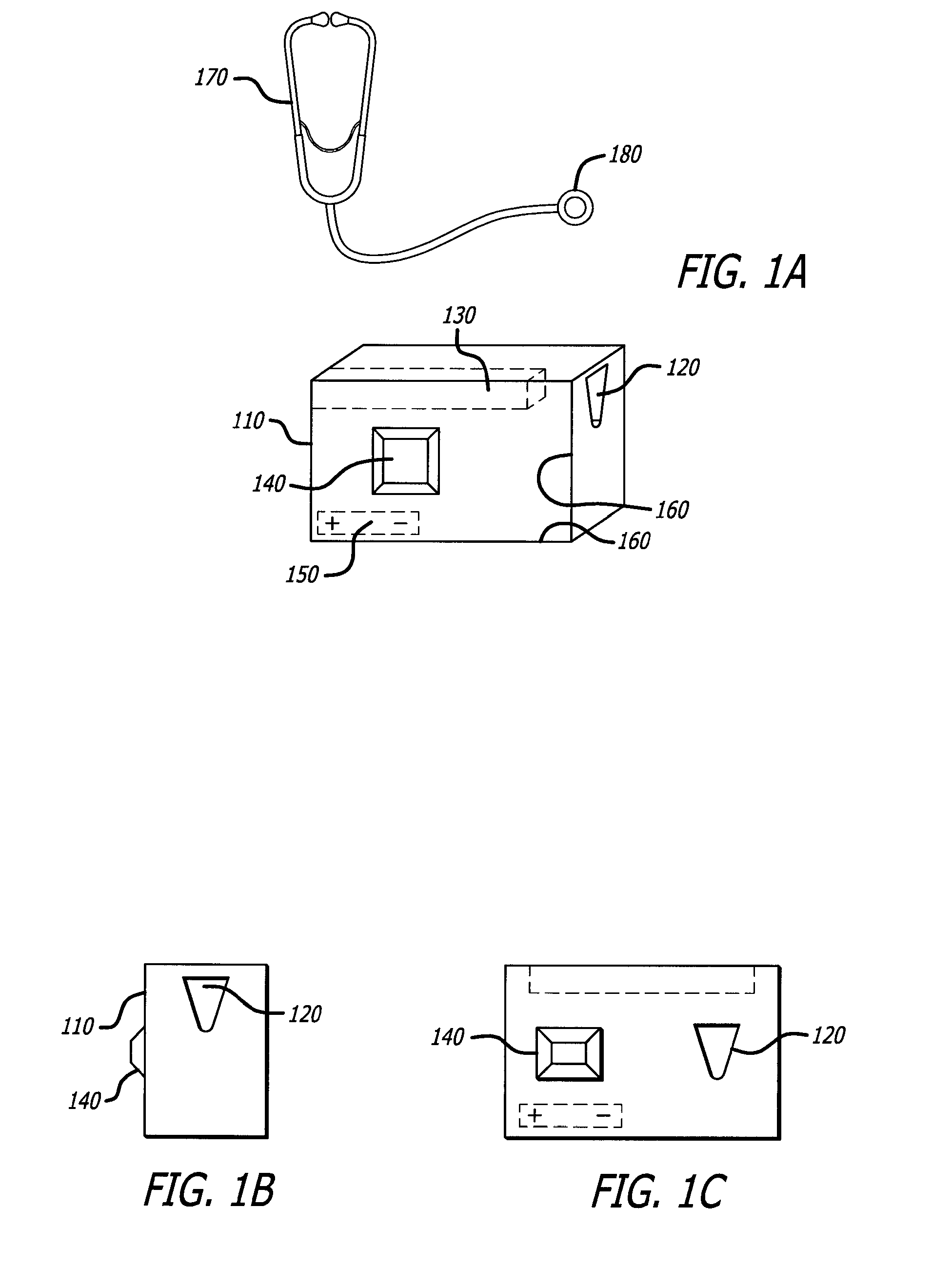
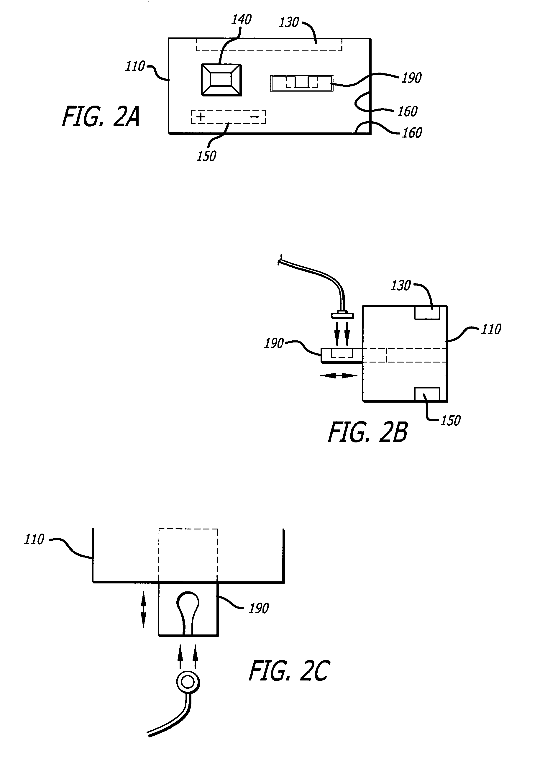
[0017]FIG. 1A shows an exemplary embodiment of the UltraViolet (UV) light sterilizing device of the present invention along with a standard stethoscope 170. The sterilizing device comprises a housing 110, opening 120, UV light source 130, control switch 140, object sensor 145, power supply 150, and reflective inner surfaces 160. The stethoscope 170 comprises a diaphragm or bell-containing head 180 that is placed in contact with the human or animal subject in order to provide medical diagnosis. While the description below references a stethoscope head as the object that is sterilized by the device, other objects can be sterilized in accordance with the device of the present invention. FIG. 1B shows a side view of the device facing the opening 120. Alternatively, as shown in FIG. 1C, the opening 120 and control switch 140 can be on the same surface of the device. The housing 110 is a hollow, rectangular body, although other suitable shapes could be used in accordance with the inventio...


PUM

PropertyMeasurementUnit
wavelengthaaaaaaaaaa
diameteraaaaaaaaaa

Abstract

In accordance with the present invention, a device and method is provided for covering and sterilizing a stethoscope or other medical instrument for safer use. The device comprises a closed housing for shielding the object to be sterilized, a means for receiving the object, a power supply, an ultraviolet light source within the housing, and a switch for controlling that lamp.

Description

BACKGROUND OF THE INVENTION[0001]This invention relates to a method and device employing ultraviolet light to sterilize medical instruments.[0002]One common problem that hospitals face today is the spread of nosocomial infections. Many of these infections are caused by organisms that have become resistant to the anti-microbial arsenal. The nosocomial infections pose a huge health and financial burden on hospitals, doctors, and patients. People infected by these resistant organisms often have to be hospitalized for extended periods of time and pay for expensive anti-microbial medications. Furthermore, a significant percentage of infected patients are prone to ultimate health deterioration and potentially fatal consequences.[0003]Nosocomial infections are frequently caused by medical staff that inadvertently spread disease from one patient to another. Poor hand washing, re-use of medical devices, or failure to sterilize the environment, all may increase the chance of distributing the ...

Claims


Application Information

Patent Timeline
Patent Type & Authority Applications(United States)
IPC IPC(8): A61L2/10
CPCA61L2/10A61L2202/24A61L2202/122
Inventor NOORI, GILDA
Owner NOORI GILDA
Learn More