Lighting device

a lighting device and light source technology, applied in the field of lighting devices, can solve the problems of unpleasant light of the lighting device, less effective to merely increase the luminance of photopic vision, etc., and achieve the effect of reducing glar

Inactive Publication Date: 2012-10-25
PANASONIC CORP
View PDF0 Cites 9 Cited by
  • Summary
  • Abstract
  • Description
  • Claims
  • Application Information

AI Technical Summary

Benefits of technology

[0012]With such configuration, it is possible to provide a lighting device capable of alleviating glare under a mesopic vision environment.

Problems solved by technology

For that reason, it is less effective to merely increase the photopic vision luminance.
It is therefore likely that the light of the lighting device may be felt unpleasant when the lighting device exists within the view field of humans.

Method used


Image

  • Lighting device
  • Lighting device
  • Lighting device

Examples


Embodiment Construction

[0019]One preferred embodiment of the present invention will now be described with reference to the accompanying drawings which form a part hereof.

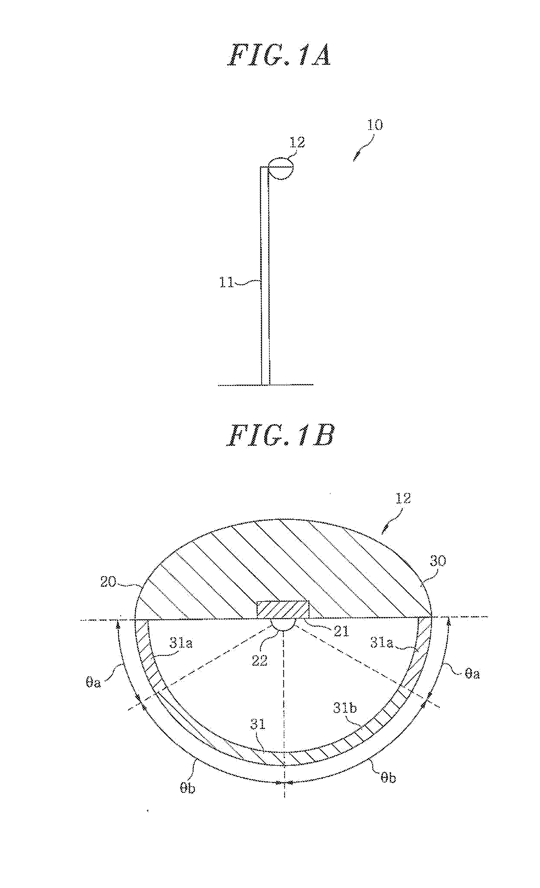
[0020]Referring to FIGS. 1A and 1E, the lighting device 10 of the present embodiment includes a cylindrical columnar pole 11 and a device body 12 attached to the tip end of the pole 11.

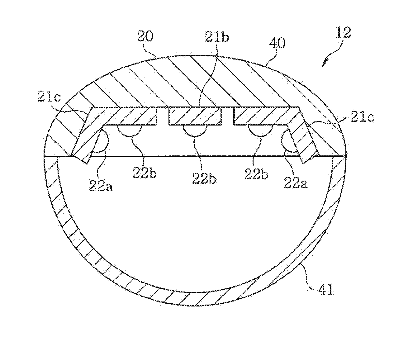
[0021]The pole 11 is used for holding, e.g., a load lamp or a street lamp, and is configured to have such a height that the device body 12 can be installed higher than the stature of a human. The device body 12 includes a housing 20, a lighting circuit 21 provided within the housing 20 and a light emitting unit 22 formed of LED elements to be turned on and off by the lighting circuit 21.

[0022]The housing 20 includes a substantially hemispherical housing body 30 to be fixed to the pole 11 by screws or the like and a substantially hemispherical globe 31 attached to the housing body 30. The housing body 30 is formed into a hemispherical shape so that, when the...


PUM

PropertyMeasurementUnit
angleaaaaaaaaaa
angle θaaaaaaaaaaa
angle θbaaaaaaaaaa

Abstract

A lighting device includes a lower irradiation portion for irradiating light mainly in a vertically downward direction and an upper irradiation portion for irradiating light more horizontally than the lower irradiation portion. An irradiation angle of the upper irradiation portion is smaller than that of the lower irradiation portion. The upper irradiation portion is configured to reduce an S/P ratio denoting a ratio of scotopic vision luminance to photopic vision luminance.

Description

FIELD OF THE INVENTION[0001]The present invention relates to a lighting device mainly used in a mesopic vision environment.BACKGROUND OF THE INVENTION[0002]In a variety of lighting devices such as a fluorescent lamp and a light emitting diode (LED element), it is typical that a design for increasing the photopic vision luminance is carried out in a bright (photopic vision) environment. This is to enable a brightness-perceiving cone to work under a photopic vision condition. By increasing the photopic vision luminance, it is possible for humans to perceive brightness in a reliable manner.[0003]Under a so-called mesopic vision environment as available in a street space or a road space at night, a rod having a spectral luminous efficiency peak value of 507 nm and capable of perceiving brightness in a photopic vision condition works in addition to the cone having a spectral luminous efficiency peak value of 555 nm. For that reason, it is less effective to merely increase the photopic vi...

Claims


Application Information

Patent Timeline
Patent Type & Authority Applications(United States)
IPC IPC(8): F21S4/00
CPCF21V3/00F21V9/08F21V13/02F21W2131/103F21Y2103/003F21S8/086F21V3/0418F21V3/0436F21Y2101/02F21V3/061F21V3/062F21Y2103/10F21Y2115/10
Inventor SAITO, TAKASHITSUKITANI, AYAKONOGUCHI, HIROKITODA, NAOHIROYAMAGUCHI, SAYAKA
Owner PANASONIC CORP
Why Eureka
Try Eureka