Multiple-input multiple-output antenna
a multi-input, multi-output technology, applied in the field of antennas, can solve problems such as hard to enhance isolation between antennas
- Summary
- Abstract
- Description
- Claims
- Application Information
AI Technical Summary
Problems solved by technology
Method used
Image
Examples
first embodiment
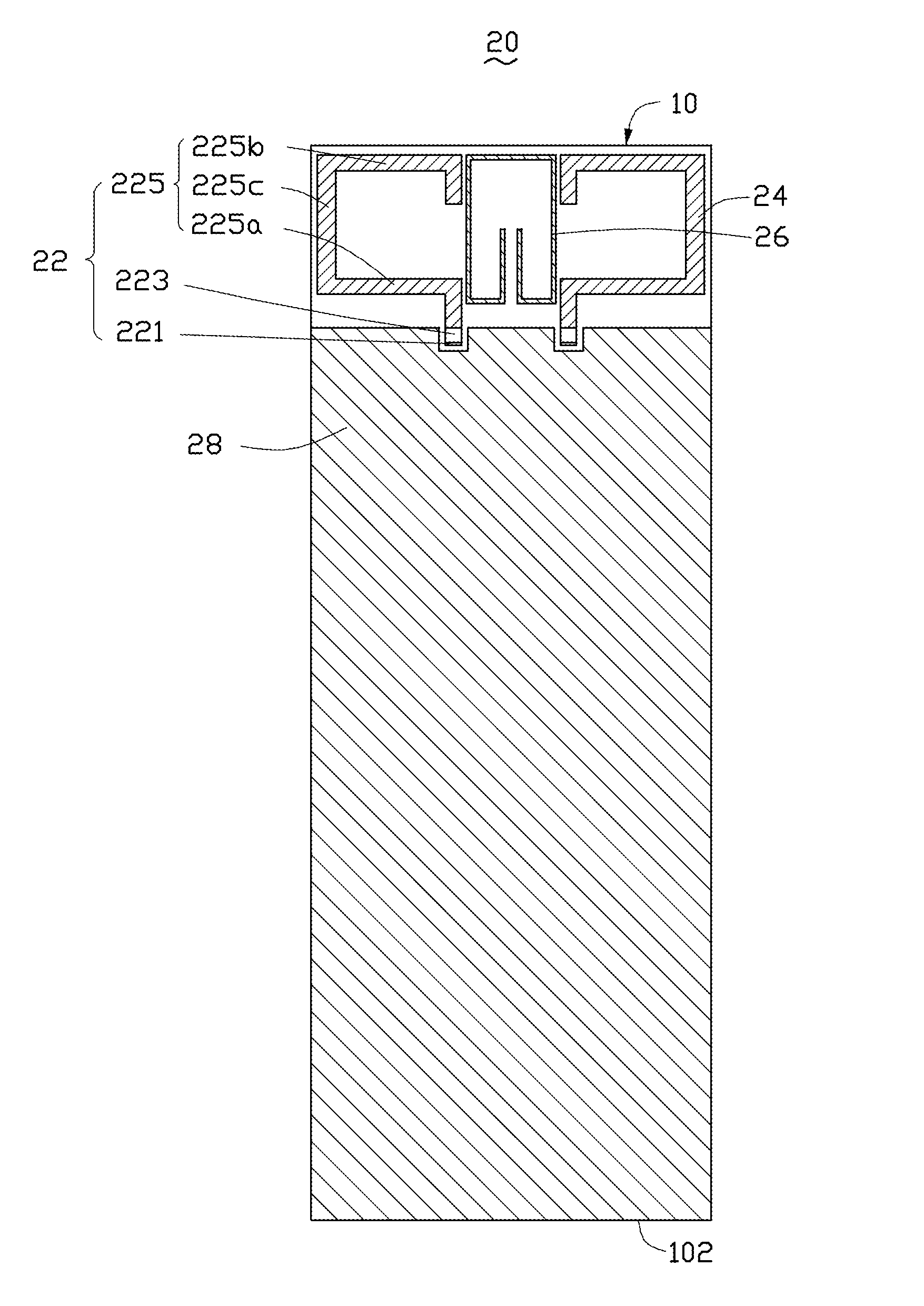
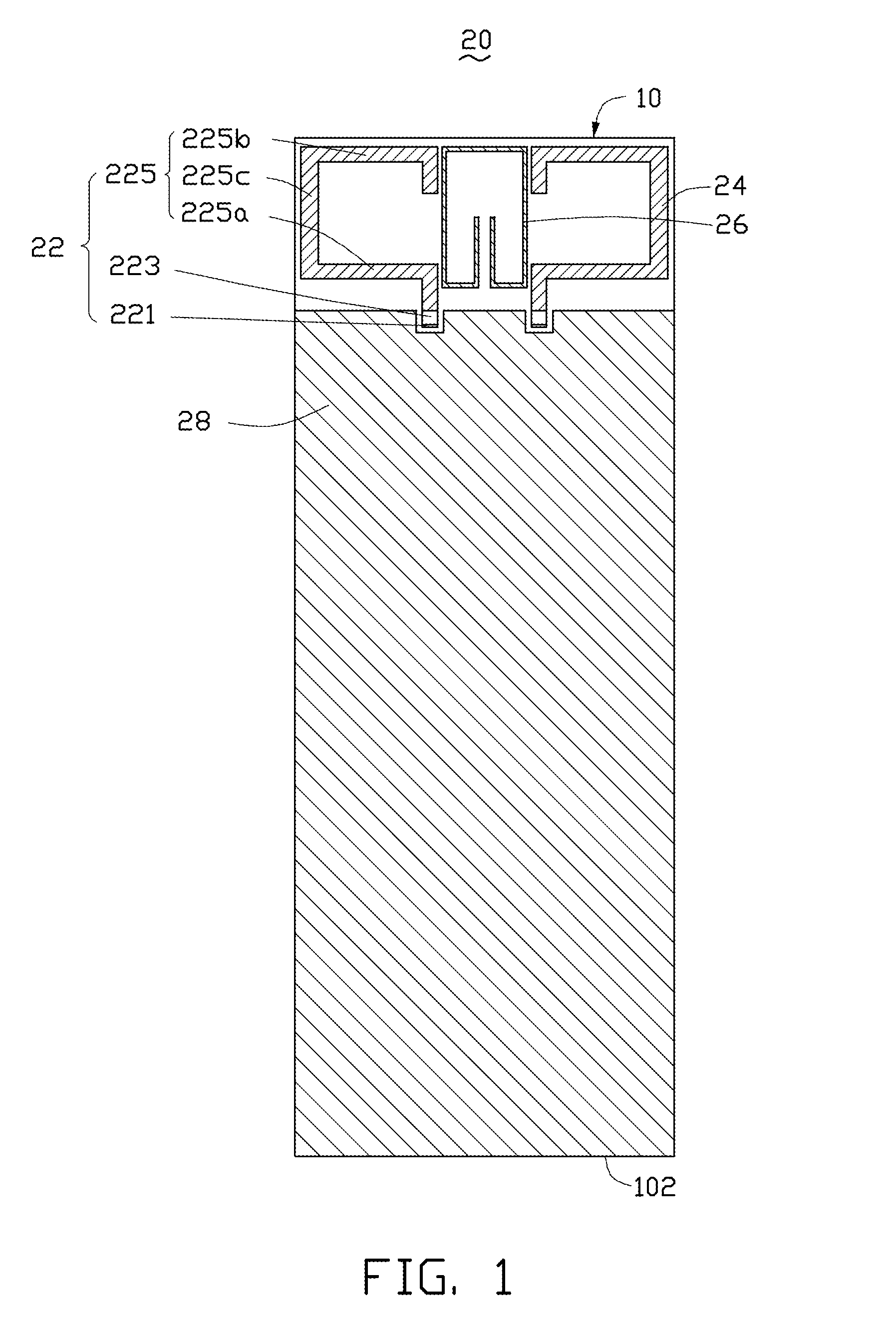
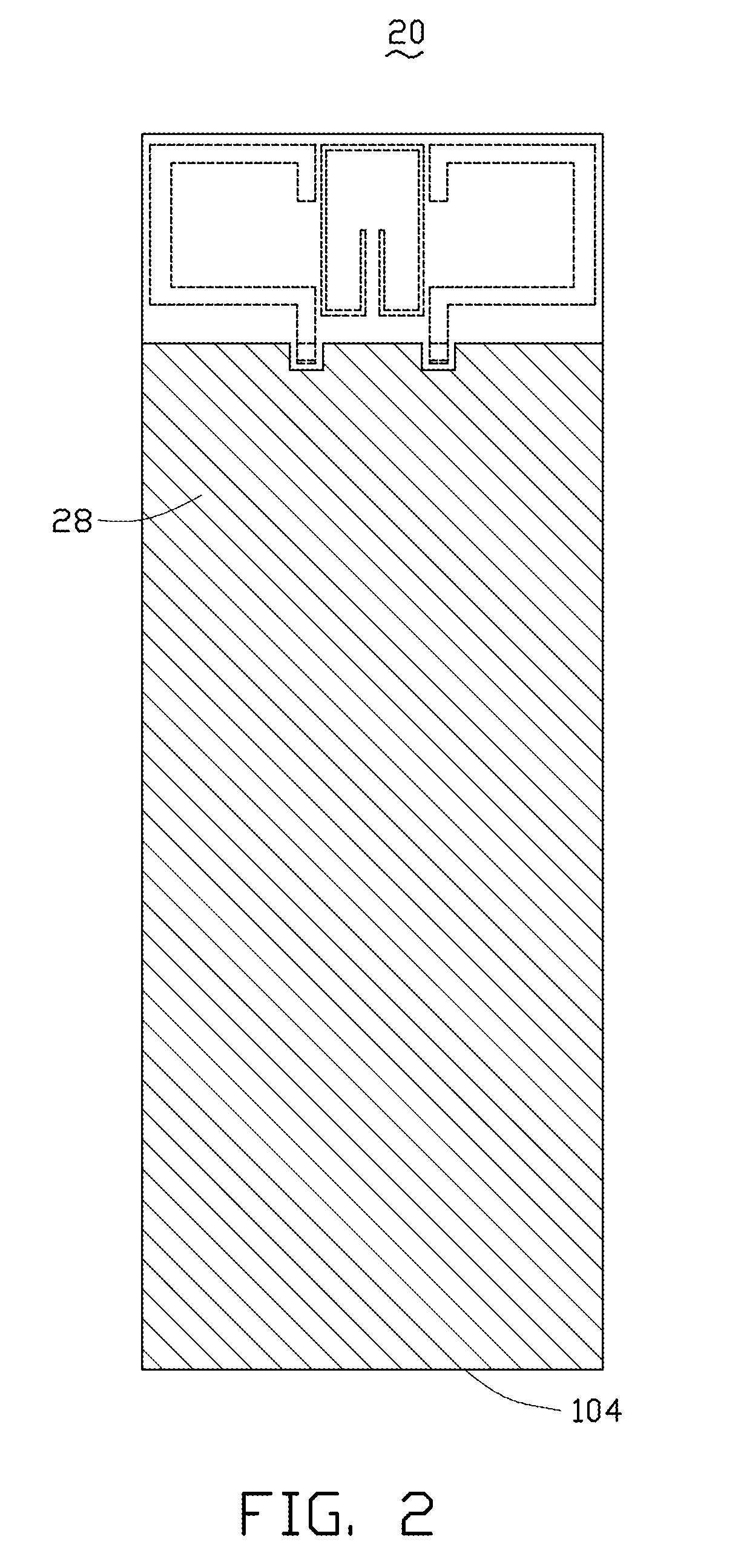
[0026]FIGS. 1 and 2 respectively show front and back views of a first multiple-input multiple-output (MIMO) antenna 20 in accordance with the present disclosure.
[0027]In the exemplary embodiment, the first MIMO antenna 20 is located on a substrate 10. The substrate 10, a printed circuit board (PCB), includes a first surface 102 (shown in FIG. 1) and a second surface 104 (shown in FIG. 2) opposite to the first surface 102. The first MIMO antenna 20 includes a first antenna 22 and a second antenna 24 defined in axial symmetry, a first coupling portion 26 and a grounding portion 28.
[0028]The first antenna 22 includes a feeding portion 221, a matching portion 223 and a radiating portion 225. The radiating portion 225 includes a first radiating part 225a, a second radiating part 225b and a third radiating part 225c. The following descriptions are presented using the first antenna 22 as the first antenna 22 has a structure symmetrical structure to the second antenna 24.
[0029]The feeding p...
second embodiment
[0043]FIGS. 7 and 8 respectively show a front view and a back view of a second MIMO antenna 420 in accordance with the present disclosure. In the exemplary embodiment, the second MIMO antenna 420 differs from the first MIMO antenna 20 shown in FIGS. 1 and 2 that the first coupling portion 26 is moved from the first surface 102 to the second surface 104, the shape of the first coupling portion 26 is adjusted to form a second coupling portion 426 and dimensions of the radiating portion 225 are changed.
[0044]The second MIMO antenna 420 includes a first antenna 22 and a second antenna 24 defined in axial symmetry, a second coupling portion 426 and a grounding portion 28. The first antenna 22 includes a feeding portion 221, a matching portion 223 and a radiating portion 225. The radiating portion 225 includes a first radiating part 225a, a second radiating part 225b and a third radiating part 225c.
[0045]In the exemplary embodiment, the second coupling portion 26 of the second MIMO anten...
third embodiment
[0051]FIGS. 12 and 13 respectively show a front view and a back view of a third MIMO antenna 620 in accordance with the present disclosure. In the exemplary embodiment, the third MIMO antenna 620 differs from the first MIMO antenna 20 shown in FIGS. 1 and 2 that the first coupling portion 26 is moved from the first surface 102 to the second surface 104, the shape of the first coupling portion 26 is adjusted to form a third coupling portion 626 and dimensions of the radiating portion 225 are changed.
[0052]The third MIMO antenna 620 includes a first antenna 22 and a second antenna 24 defined in axial symmetry, a third coupling portion 626 and a grounding portion 28. The first antenna 22 includes a feeding portion 221, a matching portion 223 and a radiating portion 225. The radiating portion 225 includes a first radiating part 225a, a second radiating part 225b and a third radiating part 225c.
[0053]In the exemplary embodiment, the third coupling portion 626 of the third MIMO antenna 6...
PUM
 Abstract
Description
Claims
Application Information
 - R&D
- Intellectual Property
- Life Sciences
- Materials
- Tech Scout
- Unparalleled Data Quality
- Higher Quality Content
- 60% Fewer Hallucinations
Browse by: Latest US Patents, China's latest patents, Technical Efficacy Thesaurus, Application Domain, Technology Topic, Popular Technical Reports.
© 2025 PatSnap. All rights reserved.Legal|Privacy policy|Modern Slavery Act Transparency Statement|Sitemap|About US| Contact US: help@patsnap.com


