
Tunable substrate integrated waveguide components

Inactive Publication Date: 2012-11-08
MCGILL UNIV
View PDF3 Cites 101 Cited by
  • Summary
  • Abstract
  • Description
  • Claims
  • Application Information

AI Technical Summary

Problems solved by technology

Unfortunately, in many of the available applications tuning is desirable, for example, to provide an antenna array with beam steering capability.

Method used


Image

  • Tunable substrate integrated waveguide components
  • Tunable substrate integrated waveguide components
  • Tunable substrate integrated waveguide components

Examples


Embodiment Construction

[0030]The following description is presented to enable a person skilled in the art to make and use the invention, and is provided in the context of a particular application and its requirements. Various modifications to the disclosed embodiments will be readily apparent to those skilled in the art, and the general principles defined herein may be applied to other embodiments and applications without departing from the scope of the invention. Thus, the present invention is not intended to be limited to the embodiments disclosed, but is to be accorded the widest scope consistent with the principles and features disclosed herein.

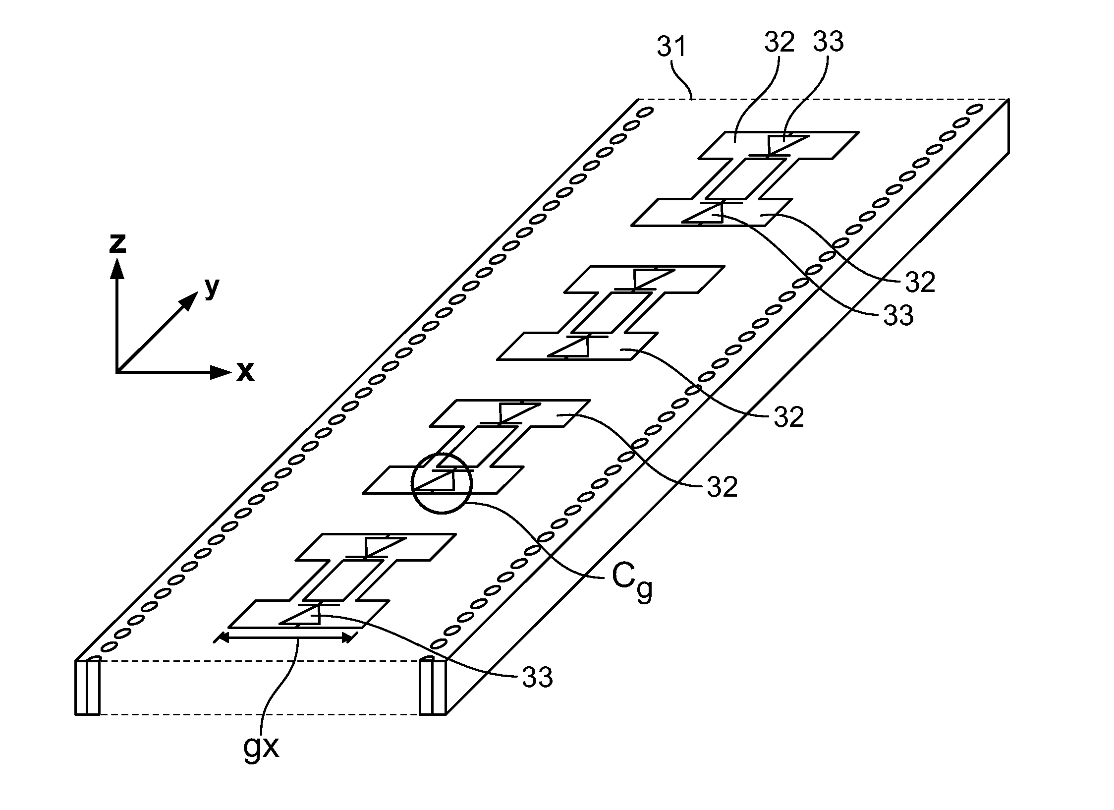
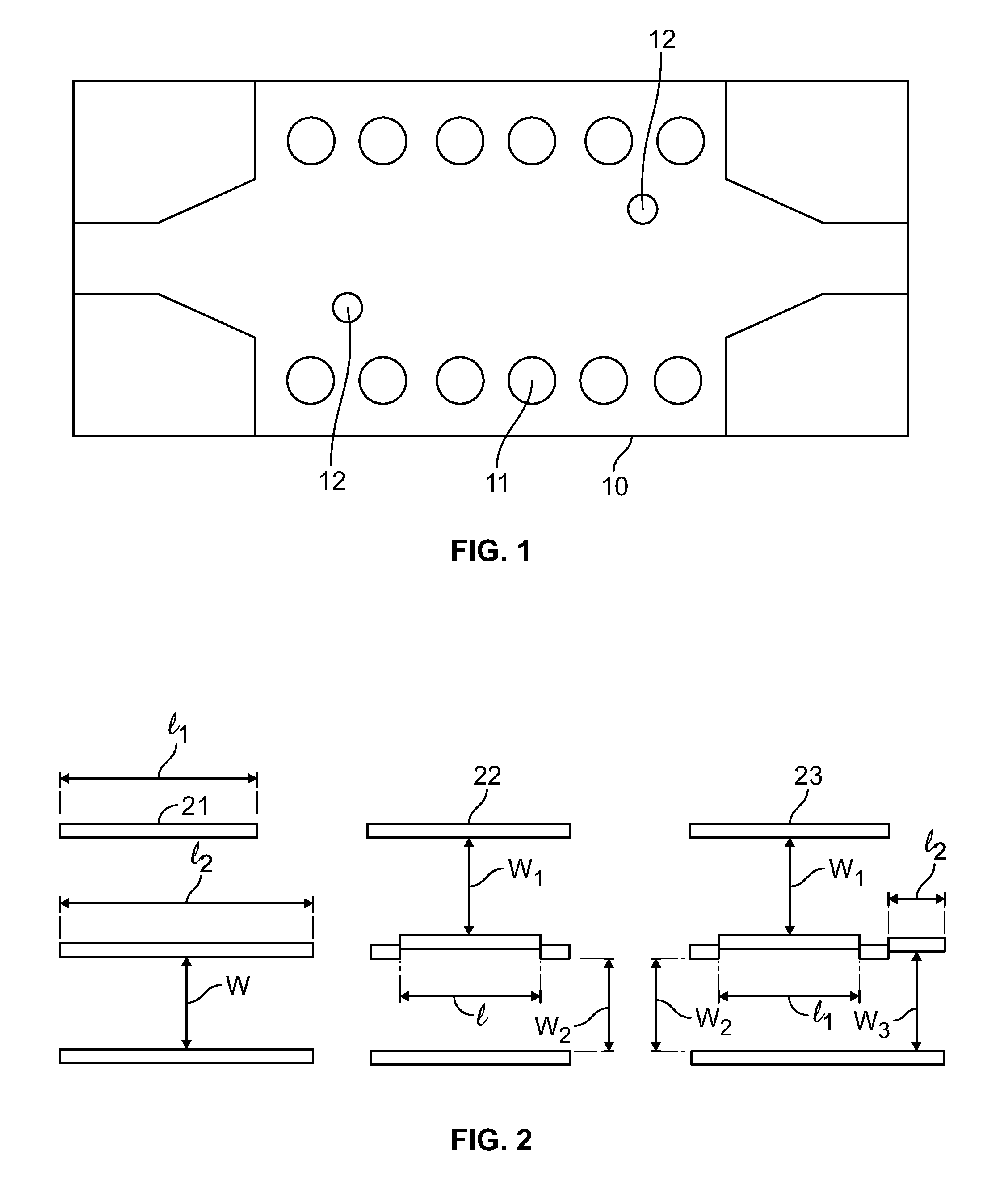
[0031]An inductive-post-based phase shifter according to the prior art is shown in FIG. 1 having two posts 12. Siderails 11 of the waveguide are provided within a structure 10. Posts 12 are arranged on the structure 10 offset from the siderails 11. This arrangement gives rise to a phase shift as a function of the position and the diameter of the metal posts. Th...


PUM


Abstract

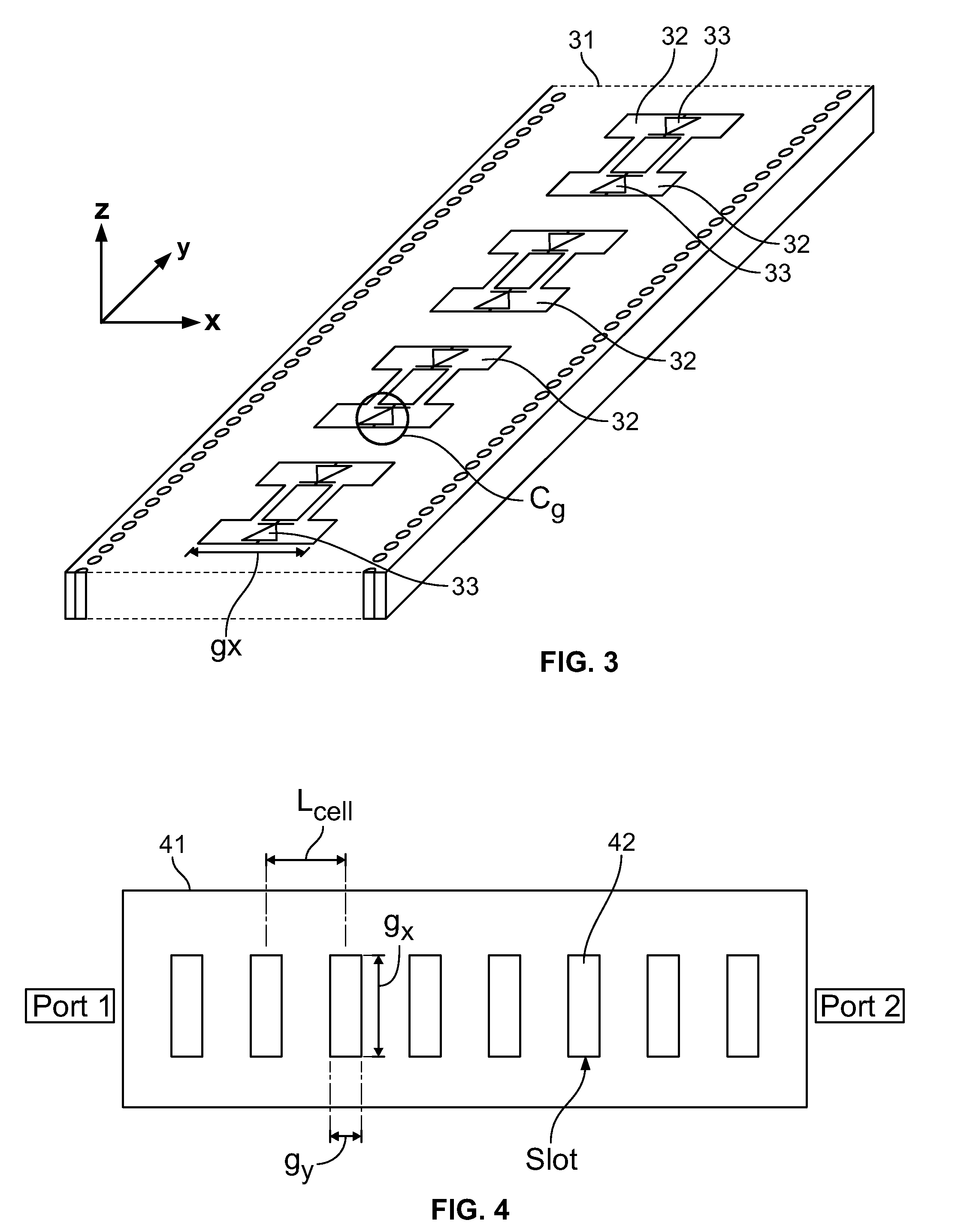
A method and an apparatus are provided for providing a tunable substrate integrated waveguide (SIW) for which a parameter of at least some element or portion thereof may be altered or varied to alter the propagation of a signal propagating through the SIW thereby achieving a tunable SIW. In some embodiments a plurality of capacitively variably loaded transverse slots achieve the tunability for the SIW.

Description

FIELD OF THE INVENTION[0001]The invention relates to integrated waveguides and more particularly to tunable substrate integrated waveguides (SIWs).BACKGROUND[0002]A SIW is known as an alternative interconnect for high-speed and high-frequency signaling. A SIW offers lower transmission losses and excellent immunity to electromagnetic interference (EMI) and crosstalk in comparison with conventional planar transmission lines. Due to its benefits in the high-frequency regime, many SIW-based components have been introduced for microwave and millimeter-wave applications such as antennas, filters, power dividers and phase shifters.[0003]These microwave components are designed to operate within a certain fixed frequency band in microwave and antenna applications. Unfortunately, in many of the available applications tuning is desirable, for example, to provide an antenna array with beam steering capability. For these applications, phase shifters within the antenna array are controllable to c...

Claims


Application Information

Patent Timeline
IPC IPC(8): H01P1/207
CPCH01P1/184H01P1/207H01P1/2016H01Q3/26H01Q21/005
Inventor ABHARI, RAMESHPAYANDEHJOO, KASRASUNTIVES, ASANEE
Owner MCGILL UNIV
Learn More