
Linking and managing mathematical objects

a mathematical object and linkage technology, applied in the field of computing environment objects, can solve the problems of difficult user experience, limited functionality of the aforementioned methods, and it is almost impossible for users to find their location

Active Publication Date: 2012-11-08
SMART TECH INC (CA)
View PDF6 Cites 21 Cited by
  • Summary
  • Abstract
  • Description
  • Claims
  • Application Information

AI Technical Summary

Benefits of technology

This solution enhances user interaction by clearly indicating linked objects, allowing for easy identification of source data and enabling the creation of cascaded links among multiple objects, improving the management and updating of mathematical objects within the system.

Problems solved by technology

When using Microsoft Excel™, a user has to select a graph and then identify the cells with highlighted border to locate the cells that the graph was generated from, which may be difficult for the user.
Moreover, if these cells are under a graph, it is almost impossible for the user to find their location.
However, U.S. Pat. No. 7,289,120 does not teach how a user can distinguish such a mark from other similar marks and how to identify the source data of a graph when multiple geometrical windows and formula windows exist in the same display screen.
The functionality of the aforementioned methods is also limited.
For example, they do not allow the user to separate a graph or a geometrical window, respectively, from the cells or formula window it is linked to.
Moreover, they do not allow the user to relate two mathematical objects of the same type (e.g., relating two graph objects).

Method used


Image

  • Linking and managing mathematical objects
  • Linking and managing mathematical objects
  • Linking and managing mathematical objects

Examples


Embodiment Construction

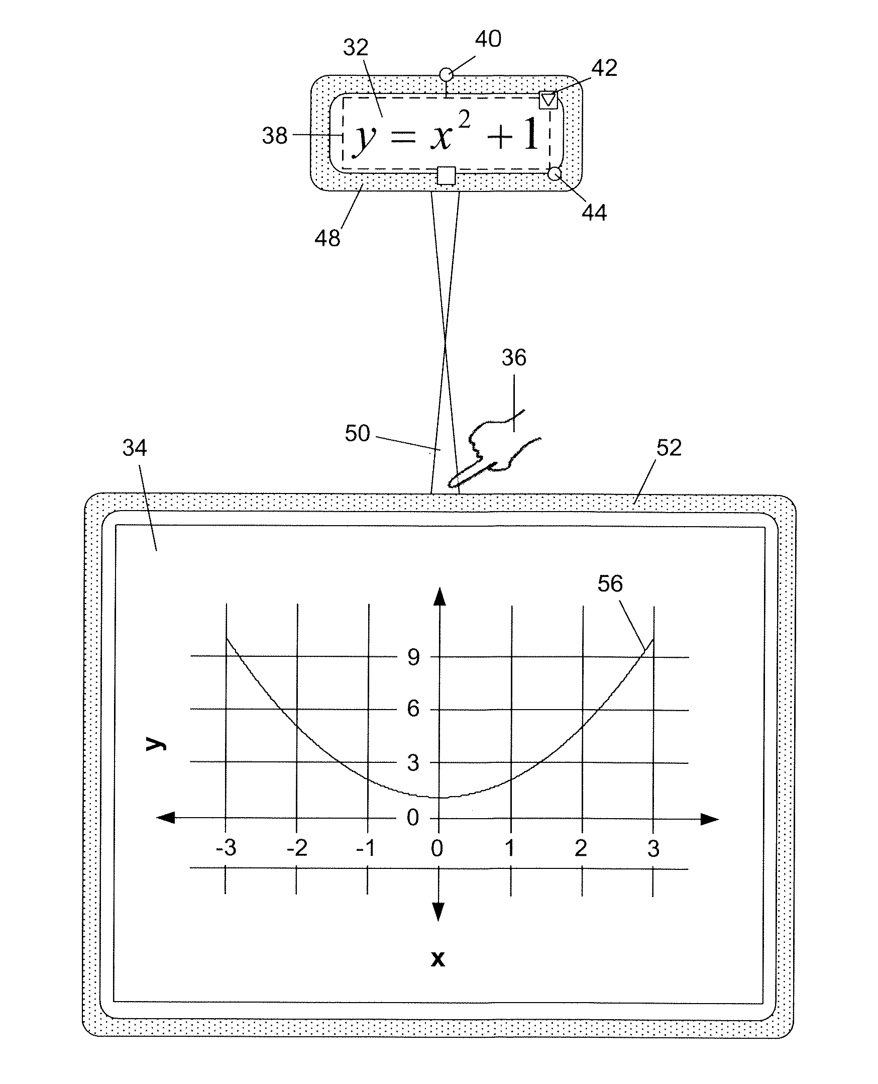
[0043]In the following, a method and tool for linking and managing mathematical objects is described. The tool is preferably implemented in software, which when executed by a processing device allows a mathematical object to be linked to another mathematical object. A visual link is then created to connect the linked objects. The software tool also allows a mathematical object to be merged into another mathematical object having the same type.

[0044]For the purposes of the following, it will be understood that a mathematical object may be, for example, a table, an equation / formula, a graph, or a shape. For clarity, a table is a set of data that may be represented in a table form with or without a border or as a matrix. An equation / formula is a character string representing a mathematical concept, or a graphical equation object representing a mathematical concept such as for example the MathType™ equation object offered by Design Science. A graph is a graphical representation of a set...


PUM


Abstract

A method for creating a second mathematical object based on a first mathematical object in a computing apparatus having a graphical user interface includes selecting a first mathematical object in response to an instruction received from a user; creating a second mathematical object using data of said first mathematical object; linking said first mathematical object to said second mathematical object; and creating a visual link between said first mathematical object and said second mathematical object.

Description

CROSS-REFERENCE TO RELATED APPLICATION[0001]This application is a divisional of U.S. patent application Ser. No. 12 / 477,485 filed on Jun. 3, 2009 the contents of which is incorporated herein by reference.FIELD OF THE INVENTION[0002]The present invention relates generally to objects in a computing environment, and in particular to a method for relating at least two mathematical objects in a computing apparatus, and a computer readable medium and interactive input system embodying the method.BACKGROUND OF THE INVENTION[0003]Interactive input systems that allow users to input ink into an application program using an active pointer (e.g., a pointer that emits light, sound or other signal), a passive pointer (e.g., a finger, cylinder or other object) or other suitable input device such as for example, a mouse or trackball, are well known. These interactive input systems include but are not limited to: touch systems comprising touch panels employing analog resistive or machine vision tech...

Claims


Application Information

Patent Timeline
Patent Type & Authority Applications(United States)
IPC IPC(8): G06F3/048
CPCG06F17/24G06F17/215G06F40/111G06F40/166
Inventor WILLEKES, TOMROUNDING, KATHRYNFORREST, GREGORY GORDON
Owner SMART TECH INC (CA)
Features
  • Generate Ideas
  • Intellectual Property
  • Life Sciences
  • Materials
  • Tech Scout
  • Unparalleled Data Quality
  • Higher Quality Content
  • 60% Fewer Hallucinations
Learn More