Tool adapter assembly and machining system

a technology of adapters and machining systems, applied in the direction of machining electric circuits, manufacturing tools, electric circuits, etc., can solve the problems of time-consuming and labor-intensive preparation of such electromachining, and inefficient exchange of cutting tools with different machining capabilities

Active Publication Date: 2012-11-15
GENERAL ELECTRIC CO
View PDF4 Cites 25 Cited by
  • Summary
  • Abstract
  • Description
  • Claims
  • Application Information

AI Technical Summary

Benefits of technology

[0007]A machining system for electromachining of a workpiece is provided in accordance with one embodiment of the invention. The machining system comprises a machining tool comprising a spindle, one or more electrodes configured to perform the electromachining, and one or more tool holding elements configure to conductively hold the respective one or more electrodes and be assembled onto the spindle of the machining tool. The machining system further comprises one or more adapters, and one or more power so

Problems solved by technology

However, in current applications, it is difficult to embed machining systems with the electromachining capabilities, it is time-c

Method used


Image

  • Tool adapter assembly and machining system
  • Tool adapter assembly and machining system
  • Tool adapter assembly and machining system

Examples


Embodiment Construction

[0015]Embodiments of the present disclosure are described herein with reference to the accompanying drawings. In the subsequent description, well-known functions or constructions are not described in detail to avoid obscuring the disclosure in unnecessary detail.

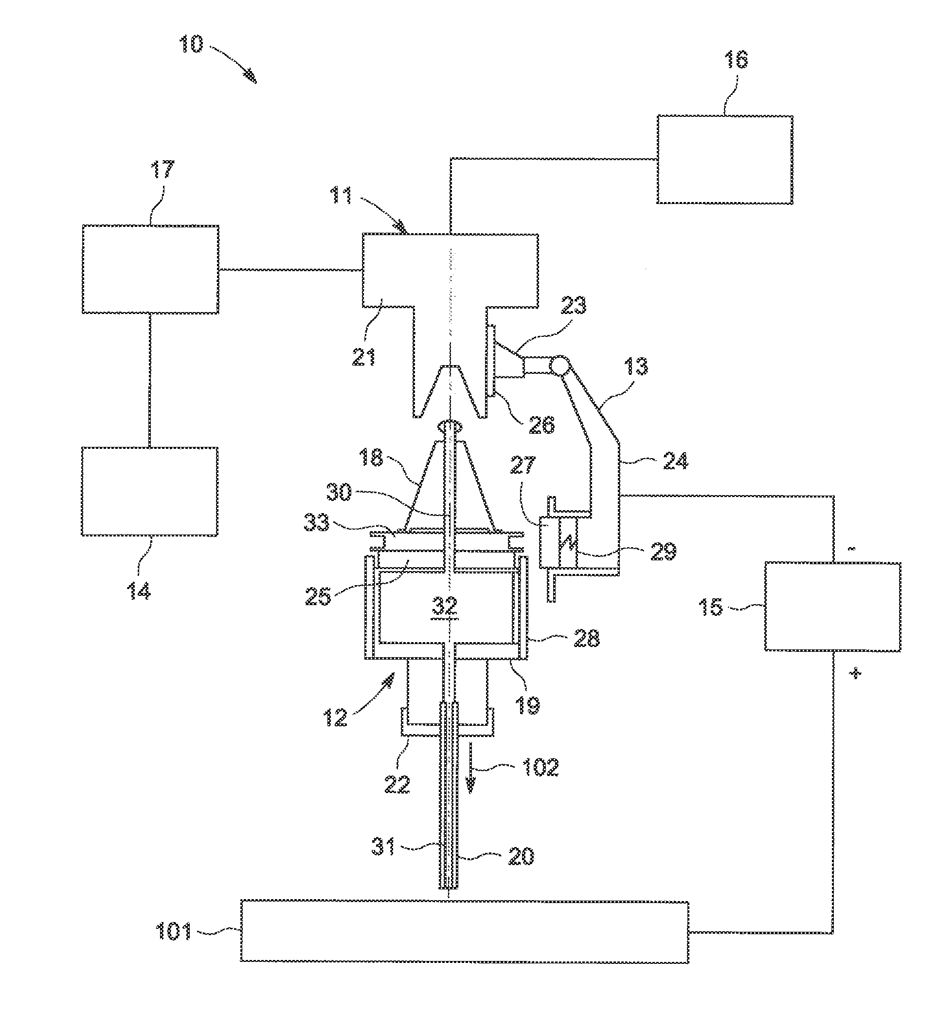
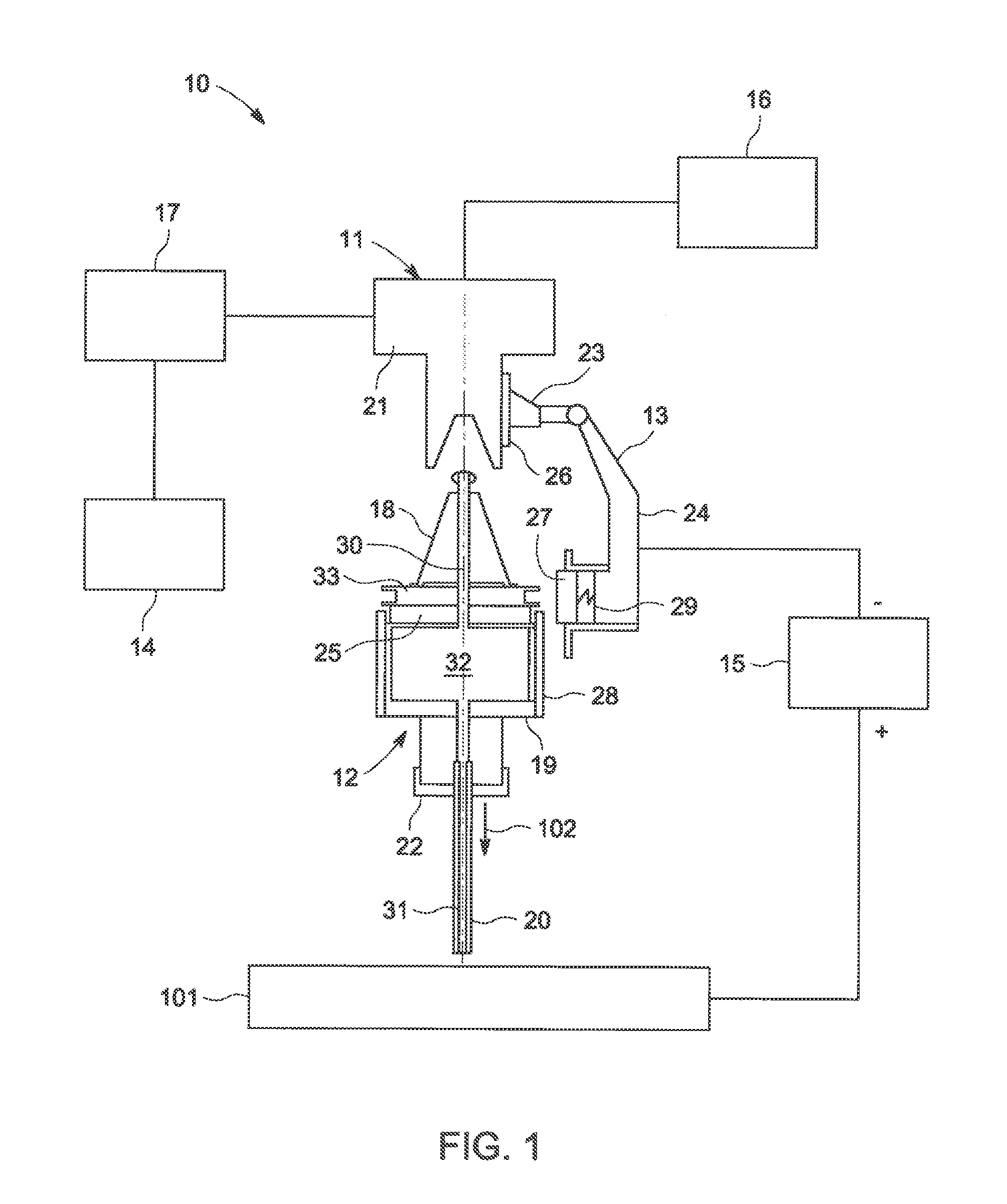
[0016]FIG. 1 illustrates a schematic diagram of a machining system 10 for machining a workpiece 101 in accordance with one embodiment of the invention. In non-limiting examples, the machining system 10 may comprise a computer numerical controlled (CNC) machine (or “machining center”) and may automatically machine the workpiece 101 according to preset control programs therein with one or more cutting tools, which may be carried in a tool storage or magazine of the machining system. In certain applications, the tool storage or magazine may not be employed.

[0017]As illustrated in FIG. 1, the machining system 10 comprises a machine tool 11, a tool adapter assembly (not labeled) comprising an adapter 13 and a tool holding element...


PUM

PropertyMeasurementUnit
Polarityaaaaaaaaaa

Abstract

A machining system is provided and includes a machining tool comprising a spindle, one or more electrodes configured to perform the electromachining, and one or more tool holding elements configure to conductively hold the respective one or more electrodes and be assembled onto the spindle of the machining tool. The machining system further comprises one or more adapters and one or more power sources configured to electrically connect to the respective one or more adapters and the workpiece. The one or more adapters are configured to conductively contact the respective one or more tool holding elements. Further, the machining system comprises one or more machining solution sources provided to pass one or more machining solutions between the workpiece and the respective one or more electrodes. A tool adapter assembly is also presented.

Description

CROSS REFERENCE TO RELATED APPLICATIONS[0001]This is a national stage application under 35 U.S.C. §371(c) of prior-filed, co-pending PCT patent application serial number PCT / US2011 / 021833, filed on Jan. 20, 2011, which claims priority to Chinese Patent Application Serial No. 201010104042.1, filed on Jan. 22, 2010, the entire contents of which are incorporated herein by reference.BACKGROUND OF THE INVENTION[0002]Embodiments of the present invention relate generally to tool adapter assemblies and machining systems employing the tool adapter assemblies. More particularly, embodiments of the present invention relate to tool adapter assemblies and machining systems employing the tool adapter assemblies for electromachining.[0003]Machining systems, such as computer numerical controlled (CNC) machines (or “machining centers”) are widely used for machining workpieces. Due to noncontact machining, higher efficiency and lower cutting tool cost, electromachining capacities are being embedded i...

Claims


Application Information

Patent Timeline
IPC IPC(8): B23H3/10
CPCB23H3/10B23H7/36B23H7/20B23H9/14B23H3/02
Inventor LI, HONGTAOWEI, BINCHEN, XIAOBINHAYASHI, STEVEN ROBERTYUAN, RENWEILUO, YUANFENG
Owner GENERAL ELECTRIC CO
Why Eureka
Try Eureka