
Lighting systems

a technology of lighting systems and lighting elements, applied in the field of lighting systems, can solve the problems of inability to determine the metered energy value of individual elements, inability to accurately value the metered energy of individual elements, etc., and achieve the effect of reducing the cost of energy consumption

Active Publication Date: 2012-11-15
SCHREDER SA
View PDF13 Cites 64 Cited by
  • Summary
  • Abstract
  • Description
  • Claims
  • Application Information

AI Technical Summary

Problems solved by technology

This means that the value of the metered energy is not accurate, with large over- and under-estimations being made of the actual energy consumed.
Moreover, the metered energy of individual elements, for example, for each luminaire, within the lighting system cannot be determined.

Method used


Image

  • Lighting systems
  • Lighting systems
  • Lighting systems

Examples


Embodiment Construction

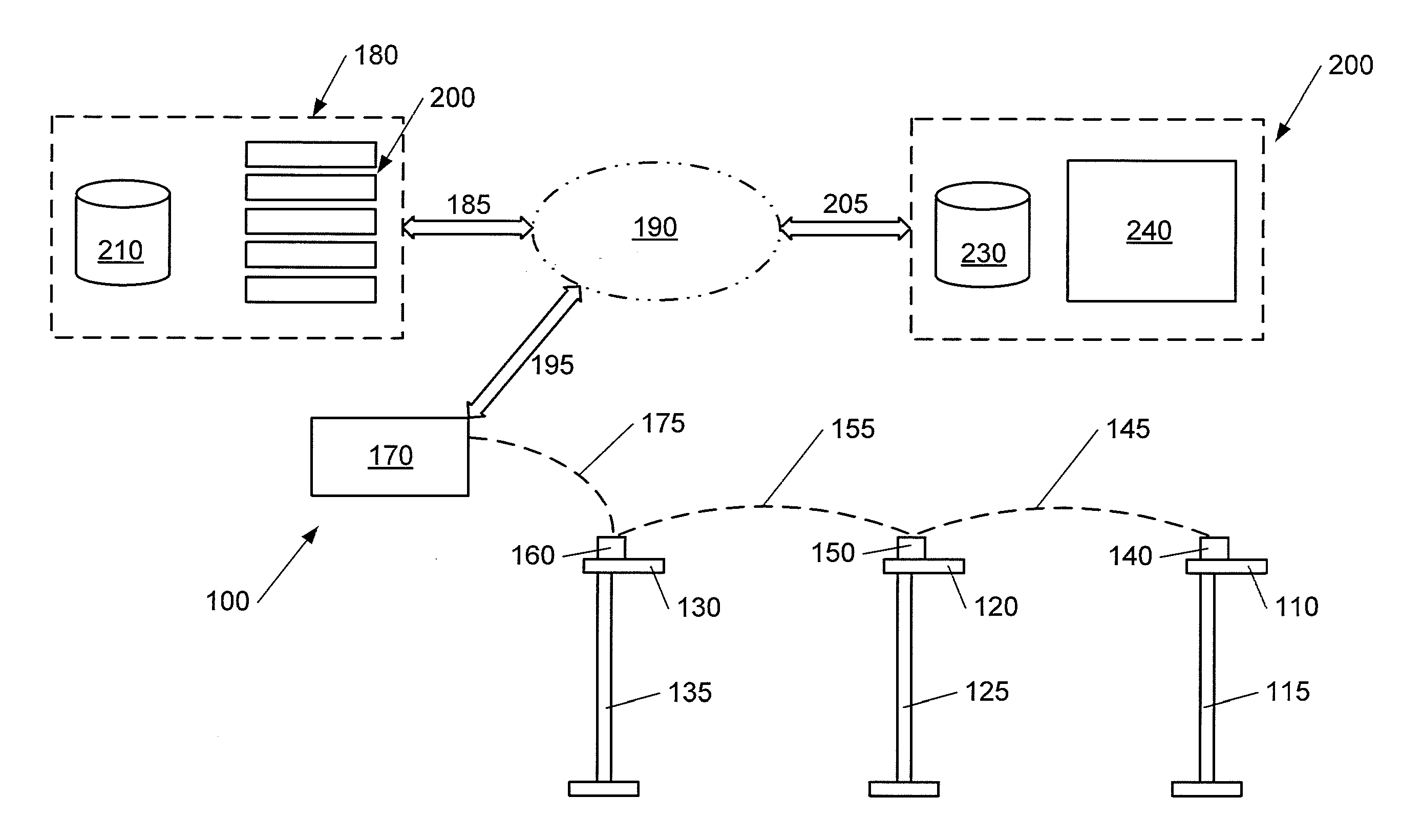
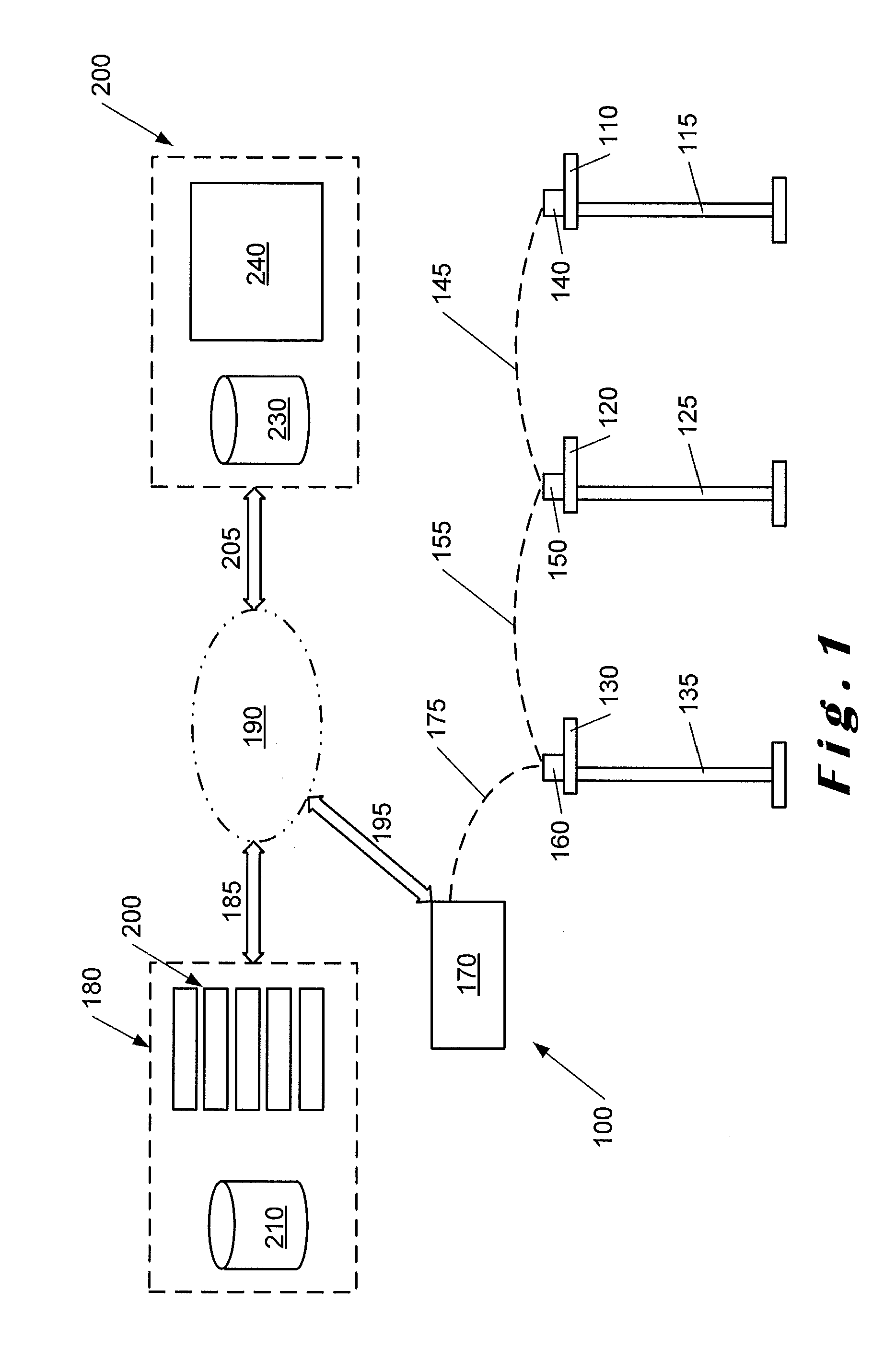
[0024]The present invention will be described with respect to exemplary embodiments, and with reference to certain drawings, but the invention is not limited thereto. The drawings described are only schematic and are non-limiting. In the drawings, the size of some of the elements may be exaggerated and not drawn on scale for illustrative purposes.

[0025]A metering circuit is disclosed which can provide more accurate measurement of the energy consumption of an associated luminaire within a lighting system.

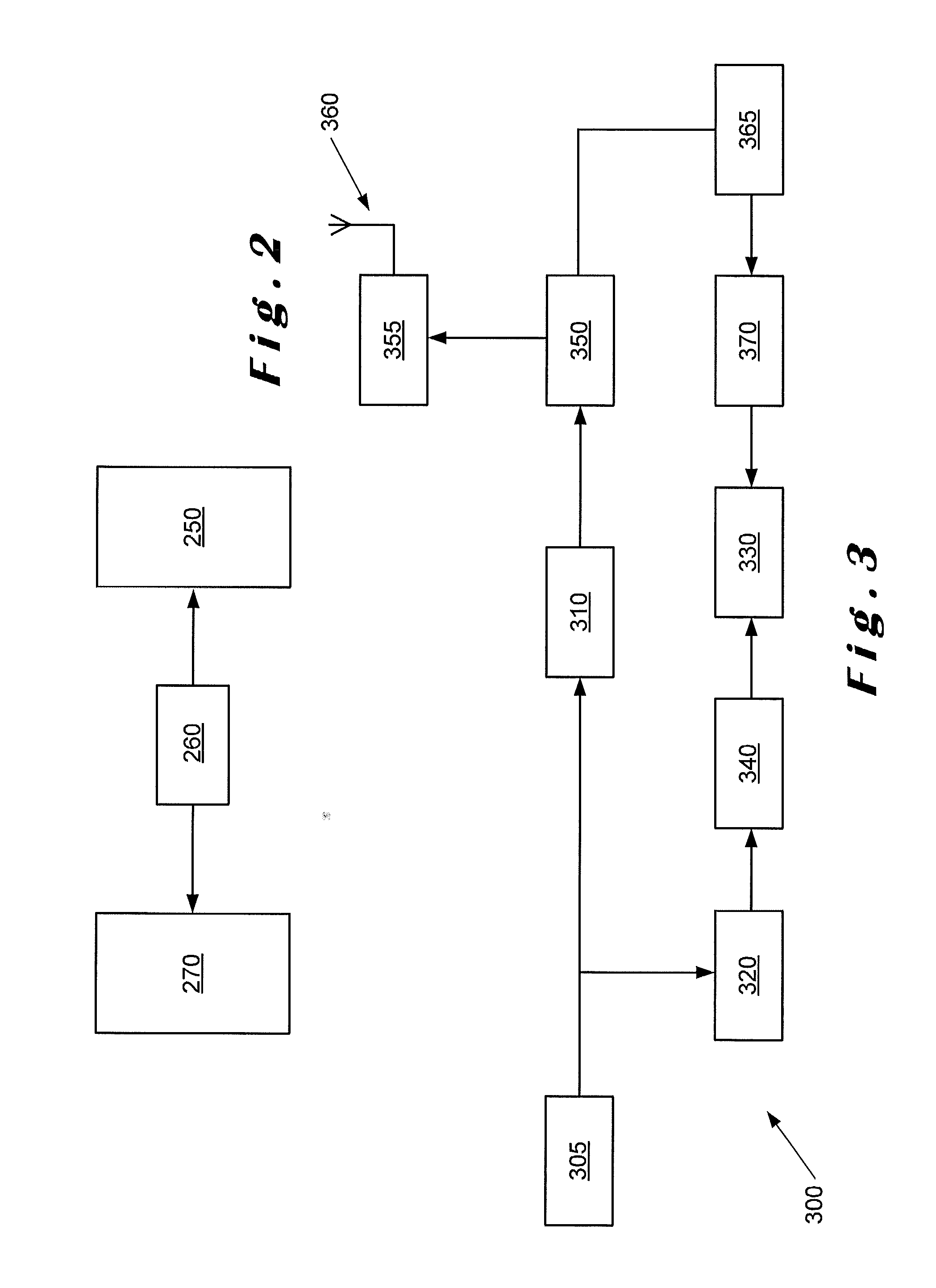
[0026]A luminaire controller including at least one energy metering circuit is also disclosed.

[0027]A lighting system as disclosed herein can include metered energy values provided for each luminaire within the system.

[0028]A processor may include a power supply connected to the processor for providing power.

[0029]In an exemplary embodiment of the present disclosure, the metering circuit is implemented as an integrated circuit.

[0030]In an embodiment, the luminaire controller comprise...


PUM


Abstract

A lighting system is disclosed having a plurality of luminaires in which the energy usage of each luminaire can individually be metered using a luminaire controller having a metering circuit.

Description

RELATED APPLICATIONS[0001]The present application claims the priority of U.S. Provisional Application Ser. No. 61 / 485,083 filed on May 11, 2011 and entitled “Lighting Unit Apparatus, Process, and Article of Manufacture”, which is incorporated by reference herein in its entirety.FIELD[0002]Improvements in or relating to lighting systems, are disclosed such as, although not exclusively, street lighting systems having energy metering functionality.BACKGROUND INFORMATION[0003]Street lighting systems may comprise a plurality of ballast lamps or light-emitting diode (LED) based luminaires. Such street lighting systems can be controlled to be turned on and turned off in accordance with the length of night and day. Such control can be provided by a simple clock or can be provided by a sensor-based system which senses the amount of ambient light and effectively switches the lighting system ON and OFF when the ambient light falls below or exceeds a predetermined threshold value.[0004]Whilst i...

Claims


Application Information

Patent Timeline
Patent Type & Authority Applications(United States)
IPC IPC(8): G01R19/00G01R13/04
CPCG01R21/133Y02B20/72H05B37/0272H05B47/19G01R19/00G01R19/2516G01R21/00G01R22/061
Inventor SCHRODER, HELMUTBRAND, DANIEL
Owner SCHREDER SA
Learn More