Zoom lens system and image pickup apparatus including the same

a technology of zoom lens and image pickup, which is applied in the field of zoom lens system and image pickup apparatus, can solve the problems of difficult to obtain a zoom lens system having a small entire system, difficult to correct various aberrations, and difficult to obtain a zoom lens system having a large system. large, high optical performance, wide angle of field

Inactive Publication Date: 2012-11-15
CANON KK
View PDF1 Cites 9 Cited by
  • Summary
  • Abstract
  • Description
  • Claims
  • Application Information

AI Technical Summary

Benefits of technology

[0008]It is an object of the present invention to provide a zoom lens system having a small entire optical system, a wide angle of field, a high zoom ratio, and high optical performance over an entire zoom range, and to provide an image pickup apparatus including the zoom lens system.

Problems solved by technology

However, such a zoom lens system has much aberration variation accompanying zooming, and it is difficult to obtain high optical performance over the entire zoom range.
In particular, it is difficult to correct various aberrations such as chromatic aberration at a telephoto end.
Unless those structures are set appropriately, it is difficult to obtain a zoom lens system having a small entire system, a wide angle of field, a high zoom ratio, and high optical performance.

Method used


Image

  • Zoom lens system and image pickup apparatus including the same
  • Zoom lens system and image pickup apparatus including the same
  • Zoom lens system and image pickup apparatus including the same

Examples


first embodiment

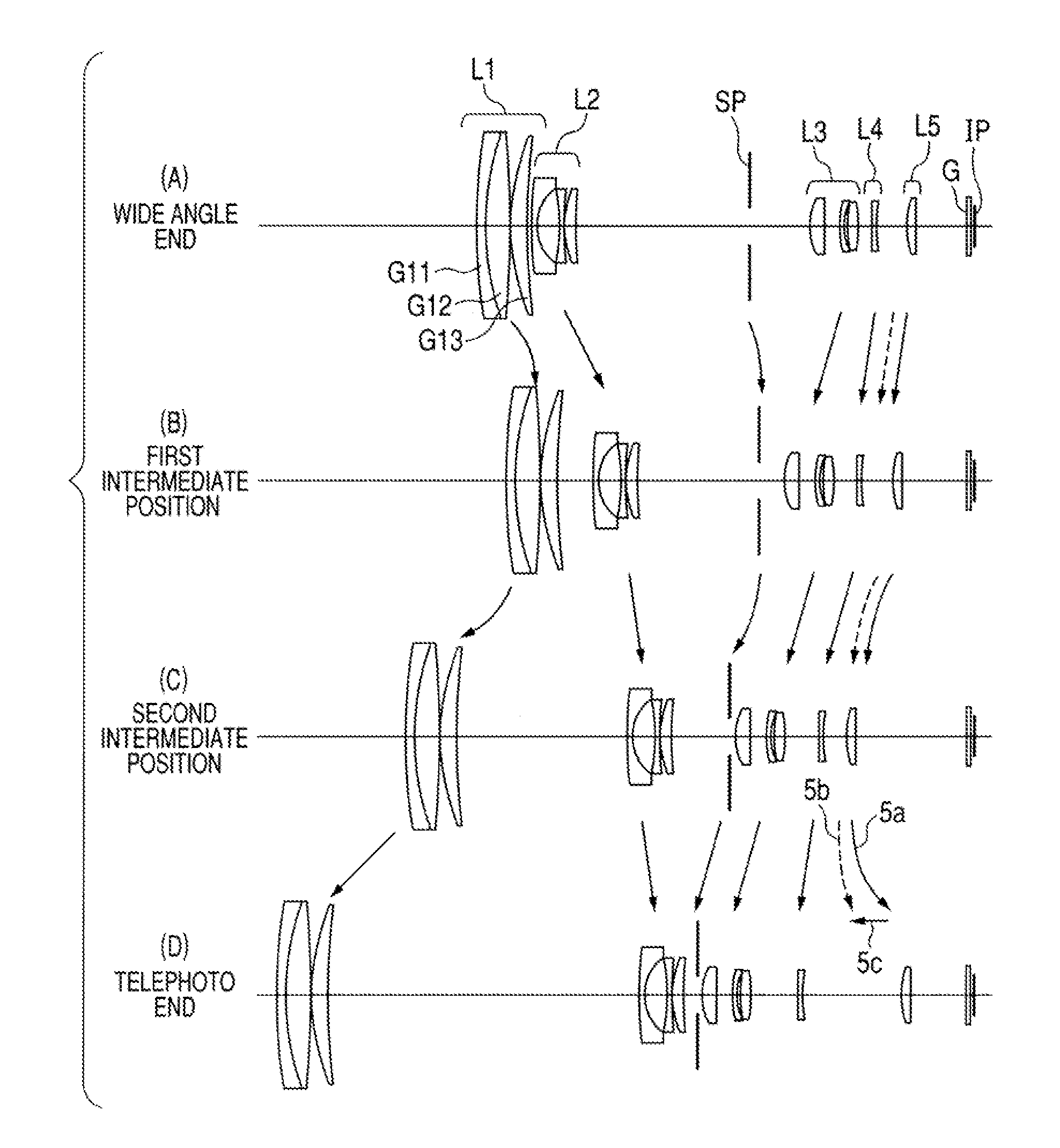
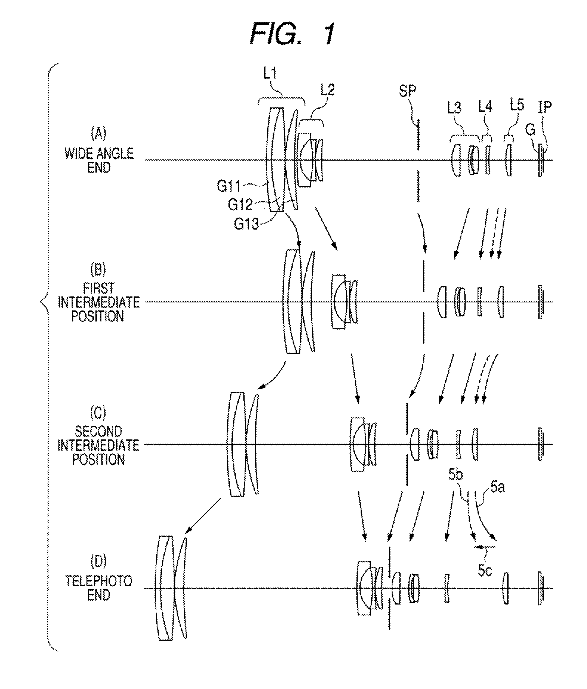
[0085]The first embodiment describes a five-unit zoom lens system including, in order from the object side to the image side, lens units having positive, negative, positive, negative, and positive refractive powers. The first lens unit L1 is constituted of a cemented lens in which the negative lens G11 having a meniscus shape with a convex surface on the object side and the positive lens G12 are cemented, and a positive lens G13 having a meniscus shape with a convex surface on the object side . The first lens unit L1 is constituted of three lenses, and hence a high zoom ratio is obtained while aberrations such as spherical aberration, longitudinal chromatic aberration, and lateral chromatic aberration can be corrected appropriately. The second lens unit L2 is constituted of three lenses including, in order from the object side to the image side, a negative lens having a meniscus shape with a convex surface toward the object side, a negative lens having a concave surface toward the i...

second embodiment

[0086]A zoom lens system according to the second embodiment is a five-unit zoom lens system similar to that of the first embodiment. The configuration of each lens unit in the zoom lens system according to the second embodiment is the same as that of the first embodiment. The fourth lens unit L4 is moved along a locus convex toward the object side in zooming from the wide angle end to the telephoto end, and hence a telephoto ratio is reduced. In the second embodiment, a half angle of field of ω=37.8 degrees at the wide angle end and a zoom ratio of 26.8 are achieved.

third embodiment

[0087]A zoom lens system according to the third embodiment is a six-unit zoom lens system including, in order from the object side to the image side, lens units having positive, negative, positive, negative, positive, and negative refractive powers. The third embodiment facilitates aberration correction at higher level by adding one lens unit to the zoom lens system according to the first or second embodiment. The sixth lens unit L6 does not move for zooming and is disposed at a position close to the image plane. Because it is sufficient that the sixth lens unit L6 is disposed close to the front side of an imaging device, the zoom lens system according to the third embodiment can be implemented without complicating the lens barrel structure of the first or second embodiment so much. The lens surface on the object side of the lens constituting the sixth lens unit L6 has an aspherical shape, and hence field curvature can be corrected appropriately. The aspherical shape may be set to t...


PUM


Abstract

A zoom lens system comprises, from an object side to an image side: a first lens unit; a second lens unit; a third lens unit; a fourth lens unit; and a fifth lens unit having positive refractive power, wherein: in zooming from a wide angle end to a telephoto end, the first, the second, the third, and the fourth lens units move so that an interval between the first and the second lens units is larger at the telephoto end than that at the wide angle end, an interval between the second and the third lens units is smaller at the telephoto end than that at the wide angle end, and a distance between the third and the fourth lens units varies; and a focal length of the first lens unit, and focal lengths of an entire system at the wide angle end and the telephoto end are appropriately set.

Description

[0001]This is a continuation of and claims priority from U.S. patent application Ser. No. 12 / 898, 790 filed on Oct. 6, 2010 which is based on and claims priority from JP 2009-232227 filed on Oct. 6, 2009 the contents of which is incorporated herein in its entirety by reference.BACKGROUND OF THE INVENTION[0002]1. Field of the Invention[0003]The present invention relates to a zoom lens system and an image pickup apparatus including the zoom lens system, which are suitable, in particular, for an image pickup apparatus using a solid-state image pickup element, such as a video camera, an electronic still camera, a broadcasting camera or a monitor camera, or an image pickup apparatus such as a silver-halide film camera.[0004]2. Description of the Related Art[0005]In recent years, an image pickup apparatus using a solid-state image pickup element, such as a video camera, a digital still camera, a broadcasting camera, or a monitor camera, as well as a silver-halide film camera has high perf...

Claims


Application Information

Patent Timeline
Patent Type & Authority Applications(United States)
IPC IPC(8): G02B15/14H04N5/262
CPCG02B15/173G02B13/009G02B15/145121
Inventor KIMURA, TOMONORI
Owner CANON KK
Why Eureka
Try Eureka