Zoom lens and image pickup apparatus including the same

a pickup apparatus and zoom lens technology, applied in the field of zoom lens and image pickup apparatus, can solve the problems of increasing total lens length and front lens effective diameter, difficult to obtain high optical performance over the entire zoom range, and achieving wide field angle, high zoom ratio, and small optical system

Active Publication Date: 2012-05-22
CANON KK
View PDF3 Cites 2 Cited by
  • Summary
  • Abstract
  • Description
  • Claims
  • Application Information

AI Technical Summary

Benefits of technology

[0009]According to the present invention, it is possible to obtain the zoom lens having a small entire optical system, a wide field angle, a high zoom ratio, and high optical performance over the entire zoom range.

Problems solved by technology

However, such a zoom lens has much aberration variation accompanying zooming, and it is difficult to obtain high optical performance over the entire zoom range.
In addition, if a movement amount of the lens unit for zooming is increased for realizing a high zoom ratio, the total lens length and the front lens effective diameter are increased, and it is difficult to obtain high optical performance over the entire zoom range.
Unless those structures are set appropriately, it is difficult to obtain a zoom lens having a small entire system, a wide field angle, a high zoom ratio, and high optical performance.

Method used


Image

  • Zoom lens and image pickup apparatus including the same
  • Zoom lens and image pickup apparatus including the same
  • Zoom lens and image pickup apparatus including the same

Examples


first embodiment

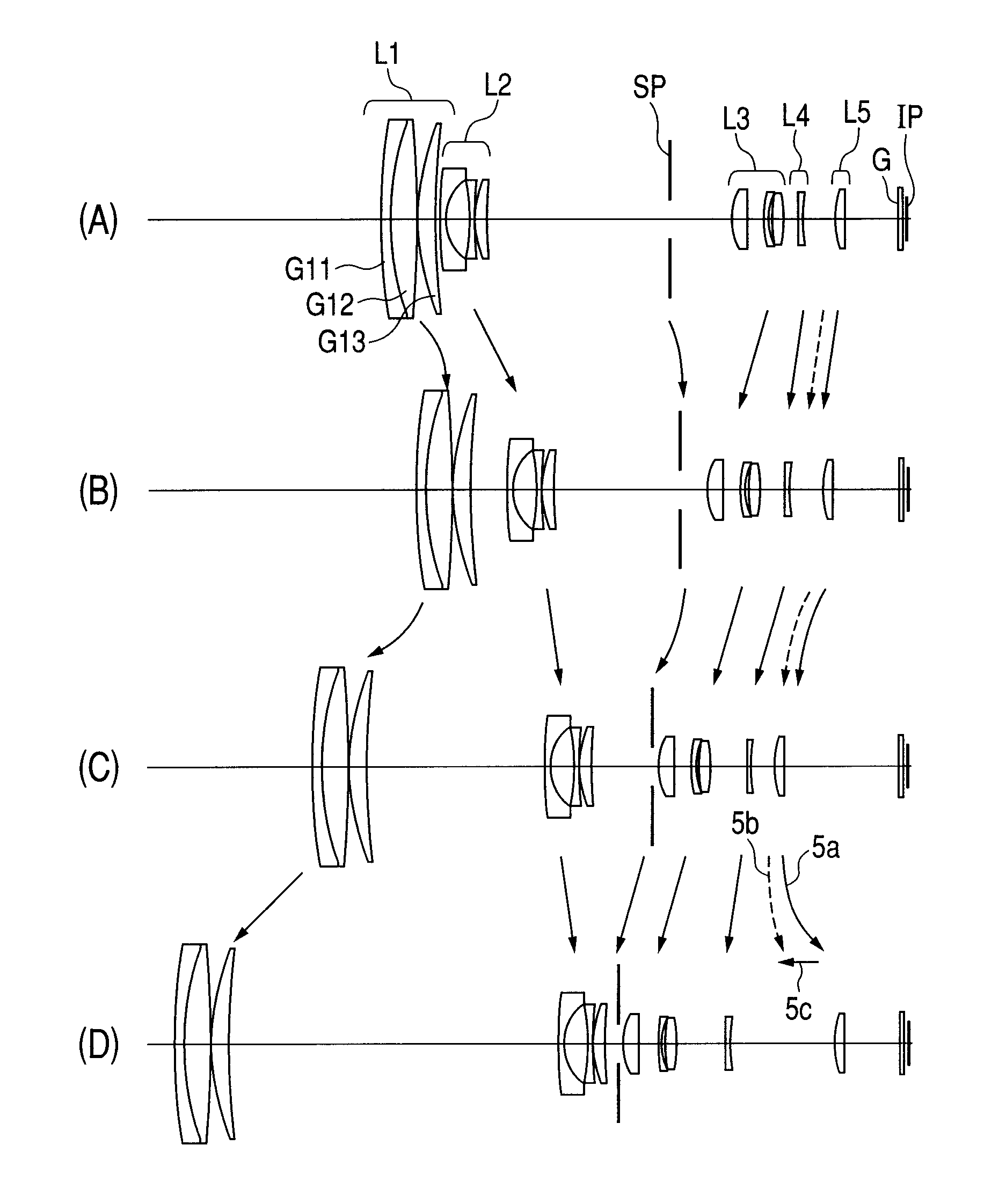
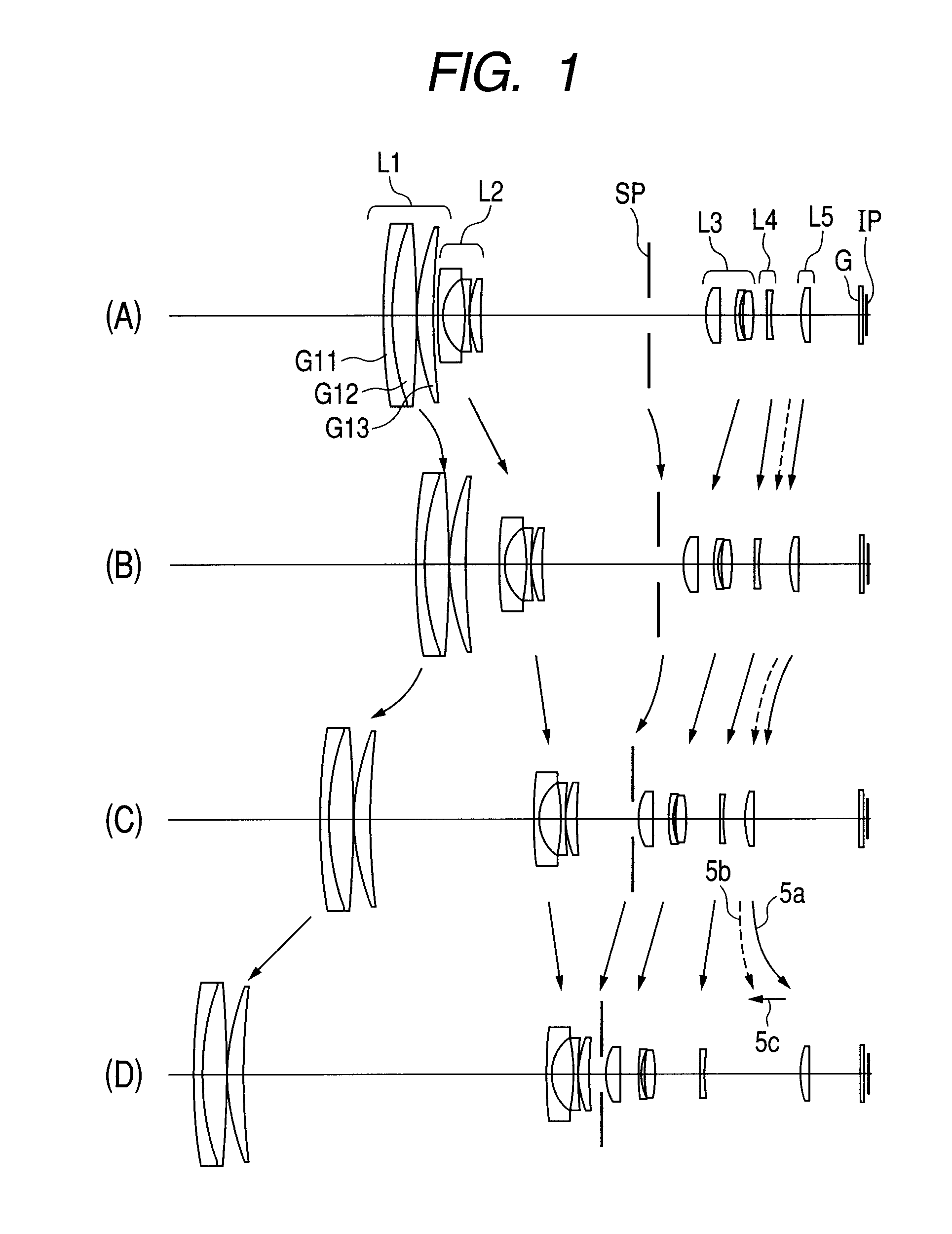
[0063]Hereinafter, with reference to (A) to (D) in FIG. 1, a zoom lens of a first embodiment of the present invention is described. The zoom lens of the first embodiment includes, in order from the object side to the image side, a first lens unit L1 having positive refractive power, a second lens unit L2 having negative refractive power, a stop (aperture stop) SP, a third lens unit L3 having positive refractive power, a fourth lens unit L4 having negative refractive power, and a fifth lens unit L5 having positive refractive power. In the first embodiment, each lens unit is moved for zooming. In this case, the interval between the first lens unit L1 and the second lens unit L2 becomes larger at the telephoto end than at the wide angle end to increase the zooming ratio of the second lens unit L2. Then, each lens unit is moved so that an interval between the second lens unit L2 and the third lens unit L3 is decreased. Thus, the third lens unit L3 has the zooming effect, and hence varia...

second embodiment

[0065]With reference to (A) to (D) in FIG. 3, a zoom lens of a second embodiment of the present invention is described. The zoom lens includes, in order from the object side to the image side, a first lens unit L1 having positive refractive power, a second lens unit L2 having negative refractive power, a third lens unit L3 having positive refractive power, a fourth lens unit L4 having negative refractive power, a fifth lens unit L5 having positive refractive power, and a sixth lens unit L6 having positive refractive power. In the second embodiment, the first lens unit L1 to the fifth lens unit L5 are moved for zooming. In the second embodiment, a half field angle of ω=44.9 degrees at the wide angle end and a zoom factor of approximately 30 are achieved. Compared with the first embodiment, one lens unit is added to be a six-unit structure, and hence higher aberration correction is facilitated. The sixth lens unit L6 does not move for zooming and is disposed at a position close to the...

third embodiment

[0067]With reference to (A) to (D) in FIG. 5, the zoom lens of a third embodiment of the present invention is described. The lens structure is the five-unit structure that is the same as that of the first embodiment. The first lens unit L1 to the fifth lens unit L5 are moved for zooming. In order to achieve an imaging half field angle of ω=45.7 degrees and a zoom factor of approximately 30 in the third embodiment at the wide angle end, the fourth lens unit L4 is constituted of a cemented lens (lens component) including a positive lens and a negative lens. Thus, variations of lateral chromatic aberration and curvature of field accompanying zooming are corrected appropriately. In addition, in order to increase an imaging field angle at a wide angle end, it is necessary to increase the refractive power of the second lens unit L2. Accompanying this, a large curvature of field in the over direction is generated in the second lens unit L2 at the wide angle end. Therefore, a surface of the...


PUM


Abstract

A zoom lens includes, in order from an object-side to an image-plane-side: a positive first lens unit; a negative second lens unit; a stop; a positive third lens unit; a negative fourth lens unit; and a positive fifth lens unit, wherein: during zooming, the first lens unit moves along a locus convex toward the image-plane-side, the second lens unit moves toward the image-plane-side, and the stop moves; at the telephoto end compared with the wide angle end, an interval between the first lens unit and the second lens unit increases, an interval between the second lens unit and the third lens unit decreases, and an interval between the aperture stop and the third lens unit decreases, focal lengths of the fourth lens unit, a focal length of an entire system at the telephoto end, and a movement amount of the first lens unit are appropriately set.

Description

BACKGROUND OF THE INVENTION[0001]1. Field of the Invention[0002]The present invention relates to a zoom lens and an image pickup apparatus including the same, which are suitable, in particular, for an image pickup apparatus using a solid-state image pickup element, such as a video camera, an electronic still camera, a broadcasting camera or a monitor camera, or an image pickup apparatus such as a silver-halide film camera.[0003]2. Description of the Related Art[0004]In recent years, an image pickup apparatus using a solid-state image pickup element, such as a video camera, a digital still camera, a broadcasting camera, or a monitor camera, as well as a silver-halide film camera has high performance, and the entire apparatus is downsized. Then, a photographing optical system used for the image pickup apparatus is required to be a high-resolution zoom lens having a short total lens length, a compact size, and a high zoom ratio. As one of the zoom lens which meet the requirements, ther...

Claims


Application Information

Patent Timeline
Patent Type & Authority Patents(United States)
IPC IPC(8): G02B15/14H04N5/262
CPCH04N5/23296G02B15/173G02B15/1461G02B15/145121H04N23/69
Inventor KIMURA, TOMONORI
Owner CANON KK
Why Eureka
Try Eureka